Countur Flange


Countur Flange |
  
|
To create a flange along a contour the SMI: Contour flange operation is used for sheet bodies.
Icon |
Ribbon |
|---|---|
|
Sheet Metal → Contour Flange |
Keyboard |
Textual Menu |
<SMI> |
Operation > Sheet Metal > Contour Flange |
The operation enables users to “glue” a flange whose cross section shape is determined by the generatrix to the sheet body. The result of this operation is added to the edges of the base sheet body.
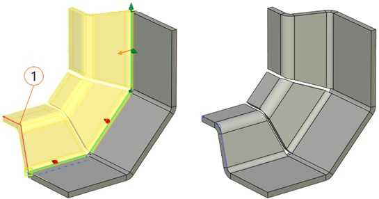
1 - Generatrix
A 3D profile, a trace or a 3D path should be chosen as an outline defining the future geometry of the flange. The generatrix cannot be closed. All of its points are to lie in one plane. The generatrix can be set by straight lines or circular arcs.
The operation requires selecting the generatrix and the edge along which the contour flange will be built. If the generatrix start does not touch the edge, it is necessary to set an adjoining point and the direction of the generatrix.
Flanges can form a closed loop. Weakening conditions and gaps at the joins of the flanges for all the body can be set.
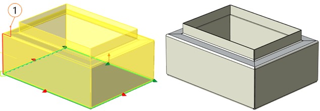
1 – Generatrix
Command parameters
Command parameters are general for sheet metal commands and are described in the corresponding subsection above. There are some minor differences in Angle and Measured parameters.
Angle. The parameter determines the outline turning in the plane perpendicular to the edge around the adjoining point. The parameter can be set by means of a manipulator or by a numerical value.
|
|
The angle from the outline |
The angle is set manually |
Measured. This parameter is inactive. The system only determines the push-out direction for the material thickness. If the edge determining the outline position at the workpiece is the upper edge of the workpiece, push-out is realized downwards. Vice versa, if the selected edge is the bottom edge of the workpiece, push-out is directed upwards.
Command automenu options are:
|
<Ctrl+Enter> |
Finish input |
|
<P> |
Set entity Parameters |
|
<X> |
Exit command |
|
<F5> |
Preview Operation Result |
|
<W> |
Draw Profile |
|
<F> |
Select Flange Guide |
|
<M> |
Add Edges |
|
<V> |
Select Adjacent Point |
|
<O> |
Select Profile Direction |
|
<A> |
Cancel Selection |
Finish input. Builds a geometry according to the given parameters. In case there are not enough parameters set, the option is not available.
Set entity Parameters. Calls a standard dialog of 3D modeling command parameters.
Exit command. Shuts down the command with cancelling all the set parameters.
Preview Operation Result. Enables/disables the standard option of 3D modeling commands review.
Draw Profile. Builds a contour flange in transparent mode. Enables users to switch to drawing at the selected work plane mode to create a profile determining the flange section. In this case when exiting the drawing at the selected work plane mode the profile created will be selected automatically. The profile should not be closed.
Select Flange Guide. Selects the 3D profile, trace or 3D path determining the flange section. The selected element should not be closed.
Add Edges. Selects the edges determining the contour position relative to the workpiece.
Select Adjacent Point. Selects a point at the profile which coincides with the edge: you should choose one of the end points of an unclosed contour.
Select Profile Direction. The option determines one of the two possible profile positions.
|
|
Variant 1 |
Variant 2 |
The direction can be set by any vector (defined by the edge, face or plane) having a meaningful component when projecting onto the plane where the profile lies. The direction of this component determines the profile direction.
Cancel Selection. Cancels all the elements selected and clears the operand window.
Building a contour flange
To build a contour flange it is necessary to follow the procedure:
●To select a generatrix – a 3D profile, a trace or a 3D path with the help of Select Flange Guide ![]() option. If the profile is not built, it can be built in the transparent mode, choosing the Draw Profile
option. If the profile is not built, it can be built in the transparent mode, choosing the Draw Profile ![]() option.
option.
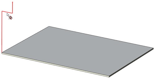
●To select the edges involved in the operation with Add Edges ![]() option. Normal to the plane where the generatrix lies either coincides with the edge or touches it in case the edge is curvilinear.
option. Normal to the plane where the generatrix lies either coincides with the edge or touches it in case the edge is curvilinear.
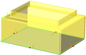
If the end point of the selected contour is at one of the selected edges, the contour flange is built right after the generatrix is selected. If necessary, you can change the contour direction with the option described below. If the end point of the contour does not belong the generatrix, set an adjoining point and the direction.
●To select a point at the contour, which coincides with the edge in the Select Adjacent Point ![]() option: one of the two end points of the unclosed contour.
option: one of the two end points of the unclosed contour.
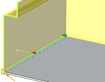
●To choose one of the two possible variants of contour direction with the help of Select Profile Direction ![]() option.
option.
●To set relief and angle machining parameters.
●To finish entering.