General Sheet Metal Commands Parameters


General Sheet Metal Commands Parameters |
  
|
All sheet metal operations have a group of common parameters. You can set default values for some of these parameters.
The main operation of working with sheet metal is bending. Many operations create geometry, which is the result of several bends in different ways or operations close to bending, but having their own characteristics. Accordingly, the dialogs of commands for working with sheet metal contain bending parameters that are the same for many operations.
Some parameters are not available to the user in a single operation, which is explained by the logic of constructing the geometry and the capabilities of the command as an analog of a real technological operation.
The parameter sets the value of the bend radius. The parameter has a custom default value. The parameter has a manipulator in the 3D scene.
If you use a profile that sets the section of the sheet, the radius value will specify the fillet at the non-rounded corners of the profile.
The parameter sets the value of the bend angle, which determines the slope of the wall of the sheet metal part. The parameter does not have a custom default value. For most of the operations, the default value of the parameter is 90°. The Toggle bend direction ![]() option allows inverting the value. The parameter has a manipulator in the 3D scene.
option allows inverting the value. The parameter has a manipulator in the 3D scene.
The parameter allows specifying the neutral layer coefficient. The parameter controls neutral factor definition upon part bending and unbending. The parameter is required for all operations that have an unfolding. The neutral layer of a workpiece is its longitudinal section, whose geometry does not change during bending.
|
1 - Workpiece 2 - Workpiece thickness 3 - Neutral layer 4 - Bend radius 5 - Bend angle 6 - Bent workpiece |
The neutral layer coefficient value can either be entered by the user or defined by the system automatically, based on the table of Neutral factors versus “bend radius/workpiece thickness” ratio. The definition is controlled by a radial-button switch. To define the neutral layer coefficient automatically, set the switcher to the Autodetect position. Setting the other button allows entering an arbitrary number in the range from 0 to 1. The value “0” means the neutral layer coincides with the workpiece face selected for bending, while “1” sets the neutral layer on the opposite face of the workpiece.
![]()
The Neutral factor dependency table is stored with the model document. You can view and change the table in the default parameters dialog for sheet metal <SPM> Defaults.
The parameter determines the position of the bend line relative to the baseline.
There are following possibilities:
●Bend start - The beginning of the bended area is aligned with the base line (used as default);
●Bend center - the middle of the bend zone of the workpiece is aligned with the base line;
●Bend end - the end of the bend zone of the workpiece is aligned with the baseline.
|
|
|
At the beginning of the bend, 1 - baseline |
In the middle of the bend 1 – bend line |
At the end of the bend 1 – bend line |
●External Dimension/Internal Dimension – the bend area is positioned in such a way that the overall size of the resulting detail is measured from the outer/inner wall of the bent/attached flange to the opposite trimmed face of the part remains the same as for the original part.
|
|
|
Workpiece 1 - baseline |
By inner size |
By outer Size |
Since the position of the baseline at the beginning of the bend zone is the most common, in the future, this option will be used to describe the possibilities of bending operations.
A baseline can be defined by two 3D points or a 3D object capable of determining a straight line. The baseline serves several purposes: it allows the system to define the body being deformed and the base face of bending, determines the position and size of the bend area, determines the possibility of creating one or another type of bending.
The baseline must lie in the plane of one of the workpiece faces being bent (normally, the top or bottom face). The baseline does not have to fully fit within the boundaries of a base face; however, at least some its portion must belong to the face.
|
|
|
Defining the baseline with an open 3D profile (1) |
Defining the baseline with the edge of the workpiece (1) |
Baseline Defining using two 3D nodes |
The face to which the baseline belongs is the base face of bending. The base face is used as the base reference when defining bending parameters.
|
1 - fixed part, 2 - bend line, 3 - bent part, 4 - rotatable part |
The boundary between the fixed part of the workpiece and the bend zone will be called the bend line.
The length of the bend line can be adjusted by Offsets from the ends of the baseline. Offsets are specified in the corresponding section of the properties window. Or they may be specified in the 3D scene using manipulators. A special flag on the right allows you to offset symmetrically.
![]()
Offsets are used when the selected baseline accurately determines the desired bend position, but its length exceeds the length of the workpiece section that needs to be bent.
|
|
|
Workpiece with 3D Profile |
Bend without offsets |
Bend with offsets |
In some cases, the use of offsets allows creating a bend even if the original baseline was incorrect. This could be, for instance, the situation, when the baseline for the bend does not fully fit in the face of the workpiece. Without using offsets, bending cannot be created in this case. By offsetting from the line end, one can reduce the length of the bend line in such a way, that the bend area fully fits in the bending base face.
|
|
Workpiece with a profile that extends beyond the edge |
Bending is built due to offset |
Four parameter variants are implemented. The selection is made from the list: Neutral layer, External side, Internal side, Flat part.
|
|
Neutral layer 1 - neutral layer, 2 - location of the flange gluing (determined by the baseline) |
External side 1 - location of the flange gluing (determined by the baseline) |
|
|
Internal side 1 - location of the flange gluing (determined by the baseline) |
Flat part 1 - location of the flange gluing (determined by the baseline), 2 - bend zone, 3 - flat part |
The parameter determines the length L calculated by the method specified by the Measured parameter. The parameter has a manipulator in the 3D scene.
The parameter allows shifting the bend area and, therefore, the bend line off the baseline. The parameter has a manipulator in the 3D scene.
Depending on the sign of the offset, the bend zone moves in one direction or another from the initial position: with a positive offset - to the bent/glued part, with a negative offset - from it.
|
|
Bend without displacement, 1 - bend line, is set by two 3D nodes |
Bend with offset, 1 - bend line, 2 - baseline defined by two 3D nodes, 3 - offset |
|
|
The baselines for flange gluing and flange bending (1) match |
Offset flange, baselines for gluing flange (1) and bending (2) do not match |
Shifting the bend line often helps in the cases, when the user is not satisfied with the location of the bend area, or when bending creation is impossible in the current location.
A group of parameters by which special grooves can be defined to reduce stresses in the metal, concentrated at the bending angles.
Bending operations allow you to create a Bend Relief automatically when performing certain operations. Reliefs are divided into Corner and Isolating. Isolating relief allows you to remove stress in the bendable flange. Corner relief allows you to remove stress at the joint of the flanges and walls. Corner reliefs can be specified with a separate Corner command.
|
1 - Corner relief 2 - Isolating relief |
The Isolating type has two variations, selected from the list: Round and Linear. The Extend Relief option is available for each of the variants.
|
|
|
|
No reliefs |
Round reliefs |
Square reliefs |
Square reliefs through |
|
Isolating relief |
||
Depth and Width parameters are available to determine the geometry of the isolating reliefs. For a square relief, those define the width of the groove and the length of the groove part ahead of the bend line, respectively. In the case of the round relief, the length of the head portion of the slot is increased by the radius of the end fillet. The fillet radius is equal to half the groove width.
The rear part of a groove of any type can be arranged in one of two ways:
●to the depth equal to bend radius plus workpiece thickness;
●extended up to the borders of the workpiece (if the Extend Relief option is enabled) or to the end of the workpiece, if gluing a flange inside the workpiece with material removal by the flange length.
|
|
|
1 - bend line, S - workpiece thickness, R - bend radius, D - width, H - depth |
||
Linear Reliefs (Non-Through) |
Round Reliefs (Non-Through) |
|
|
|
|
1 - bend line, S - workpiece thickness, R - bend radius, D - width, H - depth |
||
Square Reliefs (through to edge) |
Round Reliefs (through to edge) |
|
Corner reliefs have three choices from the list: Round, Square and Welding.
|
|
|
Round |
Square |
Welded |
Corner reliefs |
||
The radius of the circular hole is equal to the radius specified in the parameters. The square hole is constructed by three or more points of intersection of the given radius circle with the planes selected for the operation.

When welding type is selected an optimal joint is formed in the bend area. The joint can be used for welding.
The parameter sets the position of the adjacent sheet faces relative to each other. From the drop-down list, you can choose one of three items: Without overlap, Overlap, Reverse Overlap.
|
|
|
Without overlap |
Overlap |
Reverse overlap |
The parameter allows you to manually set the distance between adjacent sheet faces.
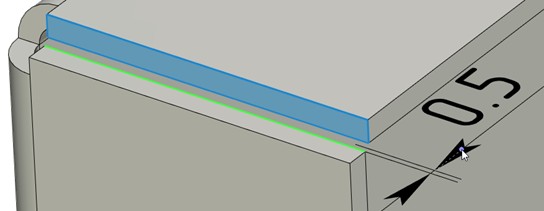
The Flange parameter group allows you to set various cropping modes during bending. The need to reduce the flange when bending and gluing the flange is indicated using the flag Flange cutting. When the flag is enabled, this mode will be activated and the gap between the part and the flange on the unfolding will be equal to the specified value, by default 0.05.
|
|
Bending after unbending |
Correct re-bending (with a decrease of the "flange") |
|
|
Removing material to the edge of the workpiece |
Removing material to the length of the "flange" |
The Limit cut to flange length flag allows you to set the method for removing the workpiece material under the flange for gluing the flange: when the flag is set (default state), the material will be removed only by the length of the flange. When the flag is disabled the material will be removed to the edge of the workpiece.
When attaching a flange, intersections may occur between the flange and the workpiece. In such a case, automatic trimming can be performed. Trimming is done in such a way to leave a diagonal gap of the specified width in the intersecting area. To perform clipping, you need to specify the Clipping option in the Type list and set the gap thickness with the Gap parameter.
When the value is set to No Clipping, intersecting parts will not be clipped.
Clipping is possible if the flange and the intersected part of the workpiece have the same thickness and lie in one plane. Certain exceptions from these rules are allowed, such as tolerance on flange thickness and bending angle when matching with the workpiece.
|
|
|
Original solid body |
Flange without clipping |
Flange without clipping |
Use manipulators. When the flag is enabled the control manipulators in the 3D scene are shown.
Show labels. When the flag is enabled the special markers informing about the current parameter values are shown, which can also be used to change the value of the operation parameters.

Dynamic preview. The flag enables/disables the dynamic preview of the command.
Bend face completely. When the flag is set, the body will be completely bent along the selected line. This parameter is important when performing operations on the sheet metal of certain geometry (for example, when it is required to bend the sheet body with a cut along the specified line).
Check self-intersections. It allows you to monitor self-intersection of bent sheet faces. When the flag is set, system will not create bend that intersects with the source body.
All manually defined elements used in sheet metal commands are displayed on the Operands tab in the options window: vertices, edges, faces and operations.
|
|
The Delete ![]() button located on the right side of the Operands tab allows you to exclude the selected item from the operation. It is also possible to delete the bend edge from the list by selecting it with a mouse click and pressing the <Delete> button on keyboard. In the working window the edge selection can be cancelled by clicking on it again with the left button of the mouse
button located on the right side of the Operands tab allows you to exclude the selected item from the operation. It is also possible to delete the bend edge from the list by selecting it with a mouse click and pressing the <Delete> button on keyboard. In the working window the edge selection can be cancelled by clicking on it again with the left button of the mouse ![]() .
.
The Up ![]() and Down
and Down ![]() buttons, located to the right below the Delete button, are used to change the order of the operation for the given elements. This feature is not required for all the commands and elements.
buttons, located to the right below the Delete button, are used to change the order of the operation for the given elements. This feature is not required for all the commands and elements.
To set default parameters for the whole group of operations for working with sheet metal, you need to call the command SMP: Default:
Icon |
Ribbon |
|---|---|
|
Sheet Metal → Defaults |
Keyboard |
Textual Menu |
<SMP> |
Operation > Sheet Metal > Defaults |
The command brings up the dialog box Sheet Metal Parameters. In the dialog fields, you can set default parameter values for all sheet metal operations of the created part.
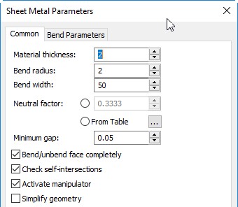
Common Tab
Material thickness. Defines the thickness of the workpiece that is used by default upon the sheet workpiece creation command.
Bend radius. Defines the default bend radius used in Bend command.
Bend width. Sets default value for the bend width.
Neutral factor (K-Factor). The parameter controls neutral factor definition for part bending and unbending. The parameter value can either be entered by the user or defined by the system automatically, based on the table of Neutral factors versus “bend radius/workpiece thickness” ratio. The Neutral factor dependency table is stored with the model document. To view or edit the table, use the button ![]() . Upon pressing the button, an additional window Neutral factors opens. This window displays the Neutral factor table of the current document. It represents a tabulated dependency of Neutral factor (the column “Value”) on the ratio “bend radius/workpiece thickness” (the column “Parameter”). The Interpolation flag sets the type of table data interpolation: the set flag means linear interpolation – the Neutral factor linearly interpolated between the tabulated data; the cleared flag means piecewise constant interpolation – the Neutral factor is maintained constant until reaching the next entry.
. Upon pressing the button, an additional window Neutral factors opens. This window displays the Neutral factor table of the current document. It represents a tabulated dependency of Neutral factor (the column “Value”) on the ratio “bend radius/workpiece thickness” (the column “Parameter”). The Interpolation flag sets the type of table data interpolation: the set flag means linear interpolation – the Neutral factor linearly interpolated between the tabulated data; the cleared flag means piecewise constant interpolation – the Neutral factor is maintained constant until reaching the next entry.
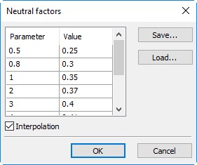
The current table can be exported into a textual file by pressing the button [Save…].
The [Load ...] button allows you to change the table by loading new data from the user-created text file “* .tnf” of the following format: the first line in the file should specify the type of interpolation: “Interpolation” - linear, “Table” - tabular. Other lines contain the table data – the “bend radius/workpiece thickness” ratios and the respective Neutral factor values. Table data can be recorded in various ways- in one row or in several, spaces or tabs can be used as delimiters. For example, the default table is written as follows:
Interpolation0.5 0.25 0.8 0.3 1 0.35 2 0.37 3 0.4 4 0.41 5 0.43 10 0.47 12 0.5 |
Once loaded from a file, the table is stored in the document of the current model and is further used in model manipulations.
Minimum gap. The parameter defines the width of a cut when creating operations with sheet metal. Defines the Reduce cutting option.
Bend/unbend face completely. This parameter is important when performing operations on the sheet metal of certain geometry (for example, when it is required to bend the sheet body with a cut along the specified line). When this parameter is enabled, the entire body along the selected line will be bent without violating the construction logic. The parameter defines the setting/removal of the default flag for the Bend face completely option in the dialog for creating bending operations.
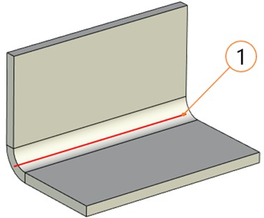
1 - Bend Line
Check self-intersections. This parameter is important when creating the «Bend» parameter. It allows you to monitor self-intersection of bent sheet faces. When the flag is set, the system will not create bend that intersects with the source body. Defines the default setting/clearing of the flag for the Check self-interactions option in bending operations.
Activate manipulator. When the flag is set for Flange, Hem, Jog operations, the value will be automatically entered via the length manipulator after selecting an edge or profile.
Simplify geometry. The parameter removes the edges that are formed as a result of flanges, hems, bridge bends, and other sheet metal operations construction.
Bend Parameters Tab.
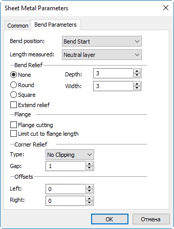
Bend position allows you to set the position of the bend zone relative to the bending baseline: Bend start, Bend end, Bend center, External Dimension or Internal Dimension. Defines the default option for the Position parameter in the bend command dialog.
Length measured. Four values of the drop-down list (Neutral layer, External side, Internal side, Flat part) allow you to set the default measurement type. The parameter defines the default variant of the Measured parameter in the bend command dialog.
The group Bend Relief defines the type and sizes of the reliefs created by default when bending.
The type of reliefs is determined by the position of the switch: None (no relief is created), Round, Square.
Depth and Width parameters allow you to set default sizes for reliefs: the depth of the front part (protruding beyond the bend line) and the width of the groove.
The flag Extend relief enables cutting of the groove to the borders of the workpiece.
Flange parameter group allows you to set default values for various cutting modes during bending. The need to cut the flange when bending and gluing the flange is indicated using the Flange cutting flag. When the flag is enabled, this mode will be activated by default. The Limit cut to flange length flag allows you to set the method for removing the workpiece material under the flange when gluing the flange. When the flag is set, by default the material will be deleted only by the length of the flange. When the flag is disabled the material will be deleted to the edge of the workpiece.
Corner Relief Group. The group allows you to enable by default cutting of intersecting parts of the flange with the workpiece. Enable the Clipping option with the specified Gap parameter (defines the default value of the Gap parameter in the bending command dialog). When set to No Clipping, overlapping parts will not be clipped by default.
Offsets parameter group. Defines the default values for Left and Right parameters. The position of the indentation (left or right) is determined by the system depending on the position of the created geometry.
Parameter values set in the command SMP: Default will be used by default in all sheet metal operations. For text and numeric parameters, this will correspond to the current value of the parameter, enclosed in square brackets, for example, Radius: [2].
During bending (after selecting the base line), auxiliary graphic elements - draggers and decorations - are displayed in the 3D scene.
Draggers are used to change sizes directly in the 3D scene. Working with draggers in sheet metal operations is similar to their use in other 3D operations and commands (extrusion, primitive, etc.). When you put the cursor on the dragger line the corresponding icon appears. If at this moment you start moving the cursor with the button ![]() pressed, the value of the corresponding parameter will change in the value input window.
pressed, the value of the corresponding parameter will change in the value input window.
|
1 - length dragger 2 - angle dragger 3 - bevel draggers 4 - radius dragger 5 - indentation dragger 6 - offset dragger of bend line 7 - direction dragger 8 - preview |
|
|
1 - Dragger 2 - Radius marker 3 - Face sequence number marker |
|
Up to eleven draggers can be in the 3D scene. However, depending on the sheet metal command used, some of the draggers may be missing.
If several elements are edited simultaneously in an operation, then to edit a specific element it is necessary to move the mouse cursor closer to the desired element. All available draggers will be displayed on the element, and the parameter window will correspond to the values of this element.
Markers - these are markers consisting of pictograms schematically depicting the operation parameter and indicating the parameter value. By clicking ![]() on the parameter value on the marker, you can call the parameter input window. Some labels allow you to change the type of parameter by clicking
on the parameter value on the marker, you can call the parameter input window. Some labels allow you to change the type of parameter by clicking ![]() on the marker. So, for example, you can use the mark to change the type of overlap in the Angle operation.
on the marker. So, for example, you can use the mark to change the type of overlap in the Angle operation.
The direction and length of the dragger, and, consequently, the geometry being created, can be attached to 3D scene objects. To do this, call the context menu of the length dragger and select one of the dragger orientation options based on 3D scene objects.
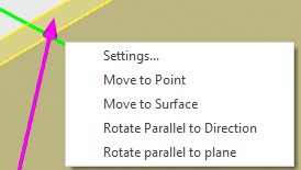
Move to Point. The length of the dragger will be determined by the length of its projection, which, in turn, is given by the selected point. After choosing the considered option in the context menu, it is necessary to indicate the 3D node or vertex in the 3D scene.
Move to Surface. The length of the manipulator will be determined by the point of its intersection with the selected surface. After selecting the considered option in the context menu, it is necessary to indicate a face, surface or workplane in the 3D scene.
Rotate Parallel to Direction. The direction of the dragger will be parallel to the selected direction. The direction can be specified by an edge or a normal to the plane. After selecting the considered option in the context menu, it is necessary to specify an edge, face, surface or workplane in the 3D scene.
Rotate Parallel to Plane. The direction of the dragger will be parallel to the selected plane. After selecting the considered option in the context menu, it is necessary to indicate a face, surface or workplane in the 3D scene.
The preview schematically shows the shape and dimensions of the created operation, dynamically changing when the command parameters are changed. With invalid parameter values, the operation preview is missing. In such cases, it is necessary to override the operation parameters. If there is no preview after setting the parameters in the 3D scene, it means that the parameters were set in such a way that the system could not find a solution. In this case, the only way is to recreate the operation.