Sketch. Creating a Non-parametric Drawing.


Sketch. Creating a Non-parametric Drawing. |
|
Use the command SK: Create Sketch for a quick graphic lines creation.
Keyboard |
Ribbon |
|---|---|
<SK> |
Drawing → Sketch |
Icon |
Textual Menu |
|
Drawing > Sketch |
The sketch line options.
Construction of Ellipses and Ellipses Arcs
Methods for Modifying Graphic Lines
Sketch Line Creation Modes.
Create lines with automatic constraining
T-FLEX CAD allows creating a drawing similar to most well-known CAD systems, using standard functionalities for creating various primitives, such as: line segments, arcs, circles, ellipses, splines. Sketcher functionalities, including object binding and dynamic tooltips, significantly simplify and speed up the process of drawing creation. With the help of a sketch, you can create a non-parametric drawing, a parametric drawing or a combination of the two specified types. Non-parametric drawings do not share the advantage of parametric drawings in the effective usage of modifiable dimensions. However, in certain cases, development of such drawings is faster, requires less resources for constructions calculation and can bring certain benefits, when large modifications are not expected.
Sketching can be used as an independent way of creating parametric drawings, and in combination with the classic for T-FLEX CAD parameterization based on the construction lines. Parameterization based on sketching with constraints makes it possible to eliminate dependence on the order of the constructions, giving the user greater freedom when working on projects. To set or remove constraints between elements, you can change the values of the model parameters at any time while designing. If you remove constraints, the parametric sketch becomes non-parametric. Conversely, after creating a nonparametric sketch on it, you can specify constraints by making parametric a drawing or its parts.
Quick creation of drawing lines (both non-parametric and parametric based on constraints) is performed using the "Sketch" command group.
When you create a sketch, the created lines are called the graphic lines.
Graphic Lines Creation

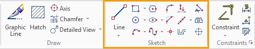
After the command is called, options for various drawing lines creation appear on the automenu panel. In the filters toolbar appears a list of active and disabled constructions. You can use all available object bindings in the system when drawing.
![]()
On the filters toolbar, on the left, there are two special icons:
●![]() Infer Constraints
Infer Constraints
●![]() Create Dimensions Automatically
Create Dimensions Automatically
The Infer Constraints creates simple constraints on graphic lines.
When working with 2D detail or 2D assembly by default, automatic constraints creation is disabled. When working with a 2D detail or a 2D assembly, a non-parametric sketch is created by default. By default, automatic constraint creation is disabled in 3D details and assembly on a normal page.
Automatic creation of dimensions is often useful when creating a parametric sketch with constraints. Enabling of this option (unlike the option of automatic creation of constraints) does not imply parametric relations creation.
When the icon ![]() is disabled, a normal non-parametric sketch is created. In the sketch creation mode, the user can construct circles, arcs, splines, or simple geometric shapes such as circles, ellipses, rectangles, polygons by selecting the sketch line options.
is disabled, a normal non-parametric sketch is created. In the sketch creation mode, the user can construct circles, arcs, splines, or simple geometric shapes such as circles, ellipses, rectangles, polygons by selecting the sketch line options.


Rectangles, polygons or sequentially entered segments, arcs and splines represent a set of separate sketch segments not connected with each other. Remember! The binding to objects that took place during construction only once, at the time of the line creation, determined the relative positions of the characteristic points and the lines themselves (segments, arcs, splines, etc.). When editing characteristic points or editing lines, the points that coincide upon construction will move independently of each other and lines that are tangent, parallel or perpendicular to each other will lose the established relationship. If, after moving the line, you need to make sure that any specific points coincide - you need to edit the position of these points. When editing, all available object bindings will be active again, as during the construction of the element. As during the construction of an element, the bindings will determine the position of the points only for the current position of the elements.

To create relations between individual sketch lines that will act independently of rebuilding, you must specify constraints (create a parametric sketch).
When creating the listed figures and lines, you must specify the required number of coordinates of characteristic points and geometric dimensions. For example, to create a segment, you need to specify the coordinates of two points or the coordinate of the first point and then the angle and length of the segment. The position of the characteristic points of the line can be specified using ![]() or by specifying coordinates in the command properties window. When specifying the position of the characteristic points of the created lines, you can use object bindings to the existing elements of the drawing (vertical/horizontal relations, tangency, perpendicularity, etc.).
or by specifying coordinates in the command properties window. When specifying the position of the characteristic points of the created lines, you can use object bindings to the existing elements of the drawing (vertical/horizontal relations, tangency, perpendicularity, etc.).
Graphic line parameters
The parameters of a graphic line can be set or changed at any time when the sketch is created or edited. The dialogue window for setting parameters is called with the automenu option, or using the context menu of a line. To bring up the context menu, click ![]() on the line.
on the line.
|
<P> |
Set graphic line parameters |
For a detailed description of the parameters, see the chapter "Graphic lines".
You can assign the same properties for similar drawing lines: holding down <Shift>, with the help ![]() , we select the necessary lines and further, in the "Elements properties" window we edit them.
, we select the necessary lines and further, in the "Elements properties" window we edit them.
In the context menu of the graphic line there is an Auxiliary option. This option makes the line invisible when you print drawing. The option is also available in the Lines dialog box and in the properties menu. If the sketch line is only needed to specify constraints or bindings, but not needed in the drawing, then when you enable the flag opposite the Auxiliary option, it becomes invisible when printing. These lines are highlighted in blue on the drawing. Example Suppose we built a hex using Infer Constraints for which the Polygon constraint was created. Suppose we need only two upper and two lower lines. If we delete two vertical lines that we do not need, the constraint will also be removed. In this case, it is convenient to make the two vertical lines invisible for printing. |
|
Properties Window
To define the coordinates of characteristic points when creating graphic lines in a command, the properties window is used. It defines the absolute, relative, polar coordinates of the created elements, as well as some geometric dimensions of the created shapes.
When you move the cursor to the drawing field, the current coordinates of the cursor are tracked in the properties window. If necessary, they can be changed in transparent mode, you may directly enter the desired value from the keyboard. The current field for entering values can be set by pointing to it with the cursor and pressing ![]() , or using the keyboard. The shortcut for navigating to one or another field in the properties window is displayed in the tooltip when you move the cursor over this field. When you enter a value in the properties window, the flag that blocks the change of the corresponding coordinate or parameter of the created element when the cursor is moved to the drawing field is automatically set. To create a point after entering coordinates just press <Enter> or
, or using the keyboard. The shortcut for navigating to one or another field in the properties window is displayed in the tooltip when you move the cursor over this field. When you enter a value in the properties window, the flag that blocks the change of the corresponding coordinate or parameter of the created element when the cursor is moved to the drawing field is automatically set. To create a point after entering coordinates just press <Enter> or ![]() in the drawing field.
in the drawing field.

When creating elements, you can use both Cartesian and polar coordinates and their combinations, so you can specify different options for arranging points in the most convenient way.
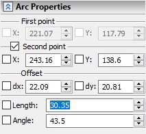
For example, when specifying the second point of a segment, you can enter the offset value and the length of the radius vector. In this case, auxiliary elements appear in the drawing: circle with the center at the beginning of the segment and the given radius and a horizontal line spaced from the first point of the segment by a distance equal to the specified displacement along the Y axis ("dy"). |
|
The points of intersection of a circle and a straight line determine possible variants of the location of the second point of a segment for given parameters. In the drawing, this is reflected as a free node that moves when the mouse moves from one point of intersection of the circle and the line to the other. When you select the desired point and click ![]() , you can finish the creation of the segment.
, you can finish the creation of the segment.
When you change the sketch option, only those parameters that are relevant for this option are displayed in the properties window. For example, the list of geometric parameters of a polygon differs significantly from the list of arc parameters.

The list of coordinates of characteristic points and geometric sizes in the properties window also depends on the stage of values input. For example, when constructing an arc, when you enter the coordinates of the first two points the properties window is the same as the window of the properties of the segment, and when the third point of the arc is selected, the list of values changes.
Object Bindings
Object bindings help to put a characteristic point when creating drawing lines. The difference in the principle of the work of bindings from the principle of the sketch creation (Tangent segment, Tangent arc, etc.) is that any creation option makes it possible to choose the option of constructing one line relative to another from an infinite set of variants, and the bindings allows to select only from specific points. Object bindings in the sketch are automatically searched for points at which the constructions are perpendicular or tangent, horizontal or vertical to the existing lines of the drawing, looking for points of the centers of arcs, circles, ellipses, midpoints, etc. Some bindings are shown by dashed lines, pointing to the characteristic points of the found geometric relation. When the binding is found, an explanatory icon appears next to the cursor. The icon simplifies the geometrical relations found. Object bindings significantly simplify drawing, and sometimes, they can replace such sketch options as Perpendicular segment, Tangent segment, etc.
The object bindings are switched on and off on the special toolbar at the top of the drawing. The toolbar automatically appears as soon as the <SK> is selected. The toolbar was already displayed above. The following bindings are available.
|
<Alt+I> |
Point on Graphic Line |
|
<Alt+D> |
Point on Construction (is not enabled by default) |
|
<Alt+P> |
Construction Intersection |
|
<Alt+R> |
Coordinate System Origin |
|
<Alt+M> |
Line Midpoint |
|
<Alt+B> |
Graphic End Points |
|
<Alt+C> |
Circle/Arc Center |
|
<Alt+A> |
Arc Angle 90, 180, 270 degrees |
|
<Alt+V> |
Horizontal/vertical tangent |
|
<Alt+H> |
Horizontal/Vertical |
|
<Alt+O> |
Orthogonal |
|
<Alt+S> |
Graphics Continuation |
|
<Alt+T> |
Tangent to Graphic Line |
|
<Alt+N> |
Snap to 3D Elements (not active for the drawing). |
By clicking ![]() on the icon
on the icon ![]() , you can disable and enable all object bindings. Each individual binding can be turned on and off by clicking
, you can disable and enable all object bindings. Each individual binding can be turned on and off by clicking ![]() on the corresponding icon.
on the corresponding icon.
Often bindings interfere with each other: It's hard to find the right one among the automatically offered binding variants. Then you can temporarily set only one, the desired binding. To do this, there is an icon ![]() on the bindings toolbar that displays a list of all the bindings from which you need to select the one you need. After you select the temporal binding, all other bindings will be inactive, until creation is finished using
on the bindings toolbar that displays a list of all the bindings from which you need to select the one you need. After you select the temporal binding, all other bindings will be inactive, until creation is finished using ![]() . After the construction is completed, all the bindings that are active in the bindings toolbar are available again. You can select a temporary binding using hot keys.
. After the construction is completed, all the bindings that are active in the bindings toolbar are available again. You can select a temporary binding using hot keys.
When the drawing is complex enough and there are many constructions, in order to activate the binding to those constructions that you need, you should move the cursor to the element (or several elements) in relation to which you want to create binding in the sketch command mode. If the required binding is active on the bindings toolbar, then an accurate dashed line will be drawn from the element. Next, we put a characteristic point with help of ![]() .
.
Examples
Drawing a circle in rectangle center
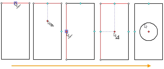
Suppose we are given a rectangle and we need to construct a circle at its center.

You need to make sure that the middle of the graphic line ![]() and the perpendicular
and the perpendicular ![]() bindings are active. Call the Circle by the center and radius option and move the cursor to the middle of the upper side of the rectangle. The binding to the center of the graphic line is activated. You move the cursor down, and the perpendicular binding icon appears. The dashed line is dynamically erased from the point of the middle perpendicular to the upper rectangle side. The binding is "remembered". Now we move the cursor to the middle of the left side of the rectangle. The binding to the middle of the graphic line is activated. You should move the cursor to the right. When the cursor is in the area close to the center - the first binding is automatically aligned from the middle of the upper side along the normal downward. The intersection of two perpendiculars from the middle of the sides is the center of the rectangle. Click
bindings are active. Call the Circle by the center and radius option and move the cursor to the middle of the upper side of the rectangle. The binding to the center of the graphic line is activated. You move the cursor down, and the perpendicular binding icon appears. The dashed line is dynamically erased from the point of the middle perpendicular to the upper rectangle side. The binding is "remembered". Now we move the cursor to the middle of the left side of the rectangle. The binding to the middle of the graphic line is activated. You should move the cursor to the right. When the cursor is in the area close to the center - the first binding is automatically aligned from the middle of the upper side along the normal downward. The intersection of two perpendiculars from the middle of the sides is the center of the rectangle. Click ![]() to specify the point of the center of the circle. Next, enter the radius of the circle.
to specify the point of the center of the circle. Next, enter the radius of the circle.
Quarter of a circle Let us create a quarter of the circle, as shown in the figure. First, you need to make sure that the bindings to the end points of the graphic line |
|
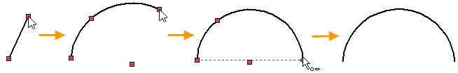
Select the Arc by two points and radius option. We specify the first point arbitrarily by using the ![]() in the drawing field. Next, enter the angle of 45° in the properties window: this means that the second point of the arc will be built on a line passing through the first point, at an angle of 45° with respect to the horizontal. We press
in the drawing field. Next, enter the angle of 45° in the properties window: this means that the second point of the arc will be built on a line passing through the first point, at an angle of 45° with respect to the horizontal. We press ![]() , thereby setting the second point of the arc.
, thereby setting the second point of the arc.

A dynamically changing arc appears under the cursor. The cursor position determines the radius of the arc. Moving the cursor, we find the binding to the arc by 90 °: the dashed lines that limit a quarter of a circle appear. Click ![]() to complete the arc. You should switch to the construction of the segment <S>. If Continuous line input has been enabled, the first point of the segment will already be at the extreme point of the arc. If the continuous input mode was not enabled, then we move the cursor to the edge of the arc, so that the binding to the end points of the line is activated. Press
to complete the arc. You should switch to the construction of the segment <S>. If Continuous line input has been enabled, the first point of the segment will already be at the extreme point of the arc. If the continuous input mode was not enabled, then we move the cursor to the edge of the arc, so that the binding to the end points of the line is activated. Press ![]() to enter the first point of the segment. The second point of the segment appears under the cursor. The line is dynamically rebuilt according to the position of the cursor. If you can not find the binding to the center of the arc, you must point the cursor to the arc. The algorithm for finding bindings should "understand" that we want to create binding to the arc. You should move the cursor to the center of the arc. Once the cursor is near the center, the binding is activated. The center point will be highlighted with a square marker and a binding to center icon will appear. Press
to enter the first point of the segment. The second point of the segment appears under the cursor. The line is dynamically rebuilt according to the position of the cursor. If you can not find the binding to the center of the arc, you must point the cursor to the arc. The algorithm for finding bindings should "understand" that we want to create binding to the arc. You should move the cursor to the center of the arc. Once the cursor is near the center, the binding is activated. The center point will be highlighted with a square marker and a binding to center icon will appear. Press ![]() to enter the second point of the segment. Depending on whether the continuous input mode is enabled or not, the first point of the next segment will be already defined or it should be set independently. After specifying the first point of the segment, we move the cursor down, toward the other extreme point of the arc. The binding to the end points of the graphic line is activated again, we click
to enter the second point of the segment. Depending on whether the continuous input mode is enabled or not, the first point of the next segment will be already defined or it should be set independently. After specifying the first point of the segment, we move the cursor down, toward the other extreme point of the arc. The binding to the end points of the graphic line is activated again, we click ![]() , the contour is built. Next, you need to create a hatch.
, the contour is built. Next, you need to create a hatch.
Continuous input of sketch elements is provided by an option in the automenu:
|
<J> |
Continuous Line Input |
In this case, the end point of the last created element (segment, arc) will be the start point for the next.
This mode is required only when creating segments and arcs. The icon of this option will be available in the auto-menu when creating rectangles, polygons, circles, ellipses or splines but it does not have any effect.
By default this option is active.
Continuous input makes the segments and arcs interconnected only at the time of construction. If you move a segment or arc, whose ends have been associated with neighboring constructions, then the ends of the segment or arc will lose their connection with the neighboring constructions. That the ends of segments, arcs, or graphic lines are connected with each other even in case of a change in their position - you need to use constraints (parameterize the sketch).
When creating graphic lines, all characteristic points (the ends of segments, spline inflection points, circle centers, etc.) are not independent nodes. It is a difference of T-FLEX CAD 16 version. Object bindings are applied for these points and they themselves can become binding objects. These points can be moved, but all actions with them are possible only within the adjustment of the graphic line: segment, arc, ellipse or spline circle. When the position of the characteristic point of the graphic line changes, the properties window of the line, to which this point belongs, automatically appears.
If you need to create an independent point of the sketch, you need to use the command:
Keyboard |
Ribbon |
|---|---|
<SK>→<Shift+P> |
Drawing → Sketch→ Point |
Icon |
Textual Menu |
|
Drawing> Sketch> Point |
To put a point you need to enter its coordinates in the properties window or specify its position using ![]() . All possible object bindings are applied to the point. The constructed point can also be a binding object for further constructions.
. All possible object bindings are applied to the point. The constructed point can also be a binding object for further constructions.
Bindings to point in the sketch have some peculiarities with respect to other graphic line bindings.
The binding to the point of the sketch line will work even if you move the sketch point, and you do not need to create constraints to do this. If, for example, you connect the ends of two segments to the sketch point, then when you move the point, the ends of the segments will move along with it. In this way, you can link the ends of segments without constraints.

Bindings to a point and to other lines will act similarly. For example, associating a circle center with a sketch point will allow you to move the circle around its center when editing the position of the point.
In this case, if you link a sketch point to graphic lines, editing the graphic lines does not change the position of the point. In order for the position of the sketch point to depend on the sketch line after editing the drawing, you need to use constraints.
Calling the Sketch command always ensures the system status ready for insertion of segments, as indicated by the icon ![]() in the Ribbon and in the automenu.
in the Ribbon and in the automenu.
Keyboard |
Ribbon |
|---|---|
<SK>→<S> |
Drawing → Sketch → Line |
Icon |
Textual Menu |
|
Drawing> Design> Line |
The presence of a black triangle in the bottom right corner indicates that this is a group of options. If you select this icon a little longer than usual, holding ![]() , a list of possible options appears.
, a list of possible options appears.

There is also a triangle that opens a list in the Ribbon under the segment icon. You do not need to hold the segment icon in the Ribbon, just press the triangle.
Line segment
To create a simple segment (option ![]() ), you need to specify two points. Points can be set arbitrarily by pointing the cursor in the drawing field and clicking
), you need to specify two points. Points can be set arbitrarily by pointing the cursor in the drawing field and clicking ![]() or specifying the exact coordinates (offsets) in the properties window.
or specifying the exact coordinates (offsets) in the properties window.
When creating a segment, you can select all available object bindings as its points.
To create a parallel segment, select the option:
|
<D> |
Parallel line |
In this case, with the help of the cursor, you need to select the line relative to which you want to create a parallel one. A dynamically movable straight line, parallel to the selected segment, will appear on the screen. If continuous input of lines mode is set, then this straight line will be parallel to the last entered line. You can refuse to select a segment by clicking ![]() .
.
After specifying the initial line, you should specify the distance to the created line, the starting point and the length of the new line. This can be done arbitrarily by moving the cursor and clicking ![]() at the desired points in the drawing field, or by entering exact values in the properties window.
at the desired points in the drawing field, or by entering exact values in the properties window.
In the properties window, you can set the coordinates of the starting point of the parallel line. This will also set the distance between the lines. A fixed line parallel to the original line will pass through the first point. The end point of the line can be set arbitrarily by moving the cursor along a straight line and clicking ![]() , or you can specify its location in the properties window (specifying either the length of the created line or a coordinate of its second point).
, or you can specify its location in the properties window (specifying either the length of the created line or a coordinate of its second point).


You can also set the distance between the lines in the properties window. In this case, the dynamic straight line will be fixed at a given distance from the initial line. The dynamic point attached to the cursor, which sets the beginning of the future line, will move along it. Its position is set by clicking ![]() . After that, you will also need to set the length of the line or a coordinate of its second point.
. After that, you will also need to set the length of the line or a coordinate of its second point.

The option of a perpendicular segment is allowed to create a perpendicular only to other lines. In this case, the perpendicular reference is first created, and then the position of the perpendicular line is specified.
|
<F> |
Perpendicular Line |
If the continuous line input mode is set, an infinite straight line will appear on the screen after selecting this option. The line is perpendicular to the last entered line and passes through its second point. This point will be the beginning of the created line. In this case, it is enough to move the dynamically moving point along the line using the cursor and fix its position with the help of ![]() (or coordinates in the properties window).
(or coordinates in the properties window).

If it is necessary to create a perpendicular to another line or to the same line, which doesn't pass through the last point, then you can decline the choice made by the system in the mode of continuous line input by clicking ![]() . Single
. Single ![]() click will cancel the selection of the starting point of the line being created. The second
click will cancel the selection of the starting point of the line being created. The second ![]() click will cancel the selection of the initial line and allow you to select the desired line. When you select a line, an endless dashed line follows the cursor. The position of this line determines the position of the segment. With the help of
click will cancel the selection of the initial line and allow you to select the desired line. When you select a line, an endless dashed line follows the cursor. The position of this line determines the position of the segment. With the help of ![]() you can fix the line and specify the first point of the segment (or set the coordinate of the point in the properties window). After that, the second point of the segment moves along a straight line following the cursor. The position of the second point is specified using
you can fix the line and specify the first point of the segment (or set the coordinate of the point in the properties window). After that, the second point of the segment moves along a straight line following the cursor. The position of the second point is specified using ![]() (or the length of the segment can be set in the properties window).
(or the length of the segment can be set in the properties window).
If you need to create a perpendicular at a specific point, then it is more convenient to use the Segment (<S>) option and object bindings. If you create a perpendicular from a specific point, then you can create a perpendicular to the tangent of any curve: arc, spline, ellipse.
Example
Create Perpendicular line to Tangent Arc
A line perpendicular to the tangent of the given arc should be created.

To do this, move the cursor to an arc in the Line <S> mode. A dynamic point will appear. The point follows the arc behind the cursor. By pressing ![]() we determine the position of the point from which we will create the segment. After that, the position of the cursor determines the coordinates of the second point of the segment. You can change the angle of the segment by moving the cursor. We find the position in which the binding of the perpendicular to the tangent arc is automatically determined. The tangent will be drawn with a thin dashed line. At the point of tangency, a perpendicularity sign will be indicated, and the icon
we determine the position of the point from which we will create the segment. After that, the position of the cursor determines the coordinates of the second point of the segment. You can change the angle of the segment by moving the cursor. We find the position in which the binding of the perpendicular to the tangent arc is automatically determined. The tangent will be drawn with a thin dashed line. At the point of tangency, a perpendicularity sign will be indicated, and the icon ![]() will appear next to the cursor. Leading the cursor along the perpendicular line we determine the length of the segment. We finish the construction by pressing
will appear next to the cursor. Leading the cursor along the perpendicular line we determine the length of the segment. We finish the construction by pressing ![]() . The exact length of the segment can be entered in the corresponding field of the properties window.
. The exact length of the segment can be entered in the corresponding field of the properties window.
In order to create a segment at a given angle to another segment, you should use the automenu option:
|
<G> |
Angle Line |
This segment is constructed similarly to the perpendicular one, with the only difference that you can set the required angle in the properties window.

A button ![]() in the properties window will allow you to flip the direction of the gradient relative to the selected segment.
in the properties window will allow you to flip the direction of the gradient relative to the selected segment.
A tangent segment can be constructed to an arc or spline. You should use the option:
|
<H> |
Tangent Line |
First, with the help of |
|
|
<К> |
Tangent line through point |
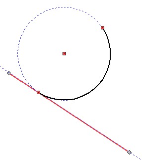
With this option, you can construct a tangent segment to any curve (circle, arc, ellipse, spline). You should select a curve using ![]() , the selected object will be highlighted (if it is an arc, then an auxiliary circle will appear on it). An auxiliary point will move along the curve. This point will be the first point of the segment and determine the point of contact. A line will be stretched from the node to the cursor. It shows the position of the created segment. In order to construct a tangent line, it is necessary to fix the position of the second point outside the circle.
, the selected object will be highlighted (if it is an arc, then an auxiliary circle will appear on it). An auxiliary point will move along the curve. This point will be the first point of the segment and determine the point of contact. A line will be stretched from the node to the cursor. It shows the position of the created segment. In order to construct a tangent line, it is necessary to fix the position of the second point outside the circle.
The position of the second point can be set either arbitrarily, by specifying the point using |
|
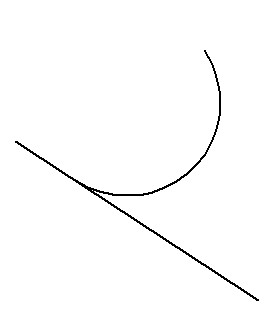
You cannot specify the second point inside the circle, inside the circular arc, inside the ellipse and inside the arc of the ellipse. In this case, the tangent cannot be constructed.
If you activate the “Automatically find tangents when creating line segments” in the Options command on the “Constraints and Dimensions” tab, then in the segment construction mode (Segment <S>) it will be possible to create tangent segments without calling the Tangent line option. A point will appear after selecting any curve on it using ![]() , and if you move the cursor away, then the point will move along the curve like when you select the Tangent line option. Further creation of the segment will be completely analogous to the method described in this subsection. If there is a binding in the place of the curve selection, then the point will not move along the curve and a tangent icon will appear near the segment. If you move the cursor away, the touch sign disappears and you can create a regular segment.
, and if you move the cursor away, then the point will move along the curve like when you select the Tangent line option. Further creation of the segment will be completely analogous to the method described in this subsection. If there is a binding in the place of the curve selection, then the point will not move along the curve and a tangent icon will appear near the segment. If you move the cursor away, the touch sign disappears and you can create a regular segment.

Keyboard |
Ribbon |
|---|---|
<SK>→<C> |
Drawing → Sketch → Arc |
Icon |
Textual Menu |
|
Design> Sketch> Arc |
Just as in the case of lines, a set of icons that allow you to create arcs in various ways is located in the submenu. In the process of creating a sketch, any of the nested icons can be displayed on the Ribbon and in the automenu. Usually this icon corresponds to the option that was called last in this command.

Arc by Three Points
|
<C> |
Arc using Three Points |
The mode for creating an arc by three points is set after the option selection. The first and the third points are the end points of the arc, and the second point determines the position of the arc.
The arc can be set arbitrarily by selecting three points using the cursor, or precisely using the properties window. In this case, the second point is given either by absolute coordinates or by offset relative to the first point of the arc. To specify the third point, you can use the absolute coordinates, radius, diameter or angle of the arc in various combinations.


Select the Arc by Two Points and Radius
To create an arc by two points, you need to activate the option in the automenu:
|
<V> |
Select the Arc by Two Points and Radius |
You need to set two extreme points of the arc using the cursor or the properties window. After that, the cursor will appear on the screen, dynamically displaying the position of the arc under construction, in accordance with the current position of the cursor. To fix the arc, you need to move the cursor to the desired position and press ![]() , or enter the angle or radius (diameter) of the arc in the properties window.
, or enter the angle or radius (diameter) of the arc in the properties window.


The arc with the center inside the circle is built in the appropriate mode, which is called using the option:
|
<B> |
Central Arc |
To construct the central arc of a circle, you should specify the center of the circle, its radius (diameter), as well as the starting and ending angles of the arc. This can be done arbitrarily, using ![]() , or precisely using the properties window. After setting the center of the circle, the dynamically moved circle will appear on the screen. In the properties window, the fields for entering the radius (diameter) and the initial angle of the arc will become available. They can also be set by moving the cursor to the desired point and pressing
, or precisely using the properties window. After setting the center of the circle, the dynamically moved circle will appear on the screen. In the properties window, the fields for entering the radius (diameter) and the initial angle of the arc will become available. They can also be set by moving the cursor to the desired point and pressing ![]() . Next, you need to move the cursor on the fixed circle in the direction in which you want to place the arc, and press
. Next, you need to move the cursor on the fixed circle in the direction in which you want to place the arc, and press ![]() again.
again.

The angle of the arc can also be set in the properties window, after which you can apply creation using the [Enter] key or clicking ![]() .
.

To create an arc tangent to the graphic line (arc or segment), you need to call the appropriate option by the icon:
|
<E> |
Tangent Arc |
After that, you need to select a graphic line. The arc will exit from the extreme point of the selected line to which the cursor was closest to at the moment of selection. In the continuous input mode, the arc will start from the end point of the last created element. Then use the cursor to move the dynamically displayed arc to the desired position and fix it by pressing ![]() .
.

The position of the tangent arc can be specified. To do this, specify the coordinates of the end point of the arc or the value of the radius (diameter) and angle of the arc in the properties window after selecting the graphic line. In the latter case, you must first set the direction of the arc using the cursor.

You need to select a line (segment, circle or arc) to which you want to ensure the contact of the created arc using this option.
|
<N> |
Arc tangent to arc |
When you select a line, it will be highlighted and continued to a full line or circle. A dynamically movable circle tangent to the selected line appears on the screen. The position and size of the circle vary depending on the position of the cursor.

The second step is to create a point outside the tangency element through which the created arc will pass. This point can be set arbitrarily by setting the cursor to the desired position and pressing ![]() or setting coordinates in the properties window. As a result, the dynamically moved circle will pass through the specified point, tangent to the line selected in the first step.
or setting coordinates in the properties window. As a result, the dynamically moved circle will pass through the specified point, tangent to the line selected in the first step.

Next, you must specify a radius (diameter) of the auxiliary circle, either by specifying a specific value in the properties window, or arbitrarily, using ![]() . As a result, the position of the auxiliary circle is fixed.
. As a result, the position of the auxiliary circle is fixed.

It remains only to specify the position of the arc itself on the auxiliary circle, between the two created points. To do this, it is enough to indicate the required position with the cursor - the dynamic image of the arc will move along with the cursor. Press ![]() after selecting the desired position. The created arc will be fixed.
after selecting the desired position. The created arc will be fixed.
|
or |
|
|
|
This automenu option allows you to create an arc tangential to two graphic lines at once (circles, arcs or segments).
|
<M> |
Arc Tangent to Two Elements |
|
|
<Space> |
|
It remains only to show the position of the arc itself on the auxiliary circle. To do this, it is enough to indicate the required position with the cursor - the dynamic image of the arc will move along with the cursor. After selecting the desired position, you should press ![]() , and the created arc locks.
, and the created arc locks.
|
or |
|
|
|
Keyboard |
Ribbon |
|---|---|
<SK> → <O> |
Drawing → Sketch → Circle |
Icon |
Textual Menu |
|
Drawing> Sketch> Circle |
As in the previous cases, this is a group of options, the list of which is presented in the attached menu under the icon. A set of options allows you to create circles of various types.

Circle by Center and Radius
Such a circle can be created using the option:
|
<O> |
Circle by Center and Radius |
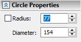
To create a circle, you should specify the position of its center and radius (diameter). You can do it using ![]() , or you can set the exact values of the coordinates of the center and radius (diameter) in the properties window.
, or you can set the exact values of the coordinates of the center and radius (diameter) in the properties window.
|
|
|
|
|
<T> |
Circle through Two Points |
This option is intended to create a circle passing through two points. You can set two points through which the circle should pass, using ![]() or by specifying coordinates in the properties window. Then you should specify the radius (diameter) of the circle. To do this, you can use
or by specifying coordinates in the properties window. Then you should specify the radius (diameter) of the circle. To do this, you can use ![]() to select the third point to determine the position and radius of the circle or use the properties window.
to select the third point to determine the position and radius of the circle or use the properties window.
|
|
|
|
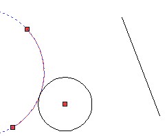
To create a circle tangent to one line (arc, circle or segment), you can use the automenu option:
|
<U> |
Circle Tangent to One Element |
The construction of the circle begins with the selection of the graphic line to which it should be tangent. The selected line is highlighted, and a dynamically movable circle tangent to the selected line appears on the screen. The position and size of the circle vary depending on the position of the cursor. In the properties window, you can set the exact coordinates of a point outside the tangency element, which determines the position of the created circle. The position of this point can be set with ![]() . Then you should specify the radius (diameter) of the circle, using
. Then you should specify the radius (diameter) of the circle, using ![]() or in the properties window.
or in the properties window.
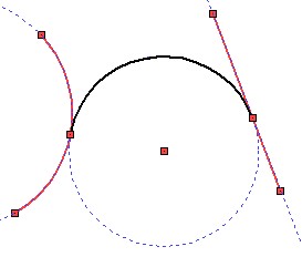
Circle Tangent to Two Elements
To create a circle tangent to two lines use the option:
|
<I> |
Circle Tangent to Two Elements |
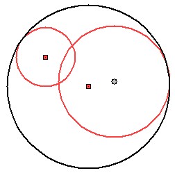
The first step for creation of a circle is a consequent selection of two tangent lines. The selected lines will be highlighted red and a dynamically movable circle tangent to them will appear on the screen. The position and size of the circle vary depending on the position of the cursor. You can change position and size of the circle using <Space> key. The position and radius of the circle can be fixed by specifying a point outside the tangent lines using ![]() or in the properties window.
or in the properties window.
|
|
|
This group of options contains a set of nested icons that allow you to create a rectangle in various ways. The created rectangles are collections of individual segments. Each such segment is edited as a separate element.

Keyboard |
Ribbon |
|---|---|
<SK>→<Shift+P> |
Drawing → Sketch → Rectangle |
Icon |
Textual Menu |
|
Drawing> Sketch> Rectangle |
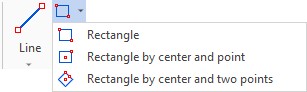
Construct Rectangle
To create a rectangle along two vertices, use the option:
|
<Shift + P> |
Rectangle |
To construct a rectangle, it is enough to set the location of its two opposite corners. Points can be set using ![]() , or by entering the coordinates in the properties window.
, or by entering the coordinates in the properties window.
Create Rectangle by Center and Point
To create a rectangle by center and vertex, use the option:
|
<Shift + C> |
Rectangle by center and point |
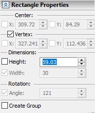
The creation of the rectangle begins with selection of the center point. The position of the point can be set directly in the drawing window, using ![]() , or entering coordinates in the properties window. Then you need to specify the position of the remaining vertices of the rectangle. This can be done by simply specifying the position of one of the vertices of the rectangle in the drawing with
, or entering coordinates in the properties window. Then you need to specify the position of the remaining vertices of the rectangle. This can be done by simply specifying the position of one of the vertices of the rectangle in the drawing with ![]() . You can also specify the exact values of the height and width of the rectangle in the properties window. In this case, you should click
. You can also specify the exact values of the height and width of the rectangle in the properties window. In this case, you should click ![]() in the drawing window or press <Enter> after setting the parameters to complete the creation of the element. You can also combine these two ways: for example, enter only the height in the properties window, and define the width by specifying a point in the drawing. Before specifying the coordinates of the second point (vertex) and applying creation, the parameters of the rectangle can be changed.
in the drawing window or press <Enter> after setting the parameters to complete the creation of the element. You can also combine these two ways: for example, enter only the height in the properties window, and define the width by specifying a point in the drawing. Before specifying the coordinates of the second point (vertex) and applying creation, the parameters of the rectangle can be changed.
|
|
|
Construct Rectangle by Center and Two Points
If you want to create a rectangle at a certain angle, then it is convenient to use not the Rectangle by center and point, but the Rectangle option at angle.
|
<Shift + A> |
Rectangle by center and two points |
The creation of a rectangle begins with specifying a point, which will be its center. You can specify a point in the properties window by specifying its coordinates, or by using ![]() . Further, a dynamic image of a segment appears, the center of which lies at the selected point. This segment sets the width of the rectangle and the angle of its side. Using
. Further, a dynamic image of a segment appears, the center of which lies at the selected point. This segment sets the width of the rectangle and the angle of its side. Using ![]() , you can set both the angle and the width value at the same time, or use the properties window to set the exact values of these parameters. If you set the width value, then an image of a circle will appear, whose diameter is equal to the specified width of the rectangle. Diametrically located points defining the position of the side of the rectangle will move along the circle. Angle can be specified using
, you can set both the angle and the width value at the same time, or use the properties window to set the exact values of these parameters. If you set the width value, then an image of a circle will appear, whose diameter is equal to the specified width of the rectangle. Diametrically located points defining the position of the side of the rectangle will move along the circle. Angle can be specified using ![]() , or set the angle in the properties window. If you specify values using the menu, you need apply changes by clicking
, or set the angle in the properties window. If you specify values using the menu, you need apply changes by clicking ![]() in the drawing window, or by pressing <Enter>.
in the drawing window, or by pressing <Enter>.
|
|
|
|
|||
The final step in creating a rectangle is to set its height. Height can be set via the properties window or in the drawing field by pressing |
|
|
||||
To construct a regular polygon, use the Polygon option.
Keyboard |
Ribbon |
|---|---|
<SK>→<Shift+R> |
Drawing → Sketch → Polygon |
Icon |
Textual Menu |
|
Drawing> Sketch> Rectangle |
Options for polygon creation are different in the Ribbon and automenu. The option is included in the same list with rectangles in the automenu. It is a separate option in the Ribbon.
The first step in a polygon creation is setting its center. The position of the point can be specified using |
|
|
|
|
|
Construction of Ellipses and Ellipses Arcs
This group of options allows you to create an ellipse in two ways and an arc of an ellipse. Both in the Ribbon and in the text menu, the group of options is combined under one icon in the drop-down list. |
|
Keyboard |
Ribbon |
|---|---|
<SK>→<Ctrl+R> |
Drawing → Sketch → Ellipse |
Icon |
Textual Menu |
|
Design> Sketch> Ellipse |
Ellipse by Center and Point
This option allows you to create an ellipse by specifying consequently its center, a point defining the length of one semi-axis of the ellipse, and the value of the second semi-axis (radius).
|
<Ctrl+T> |
Ellipse by Center and Point |
As with other sketch elements, you can set the position of points by simply clicking ![]() in the drawing field or by specifying exact values in the properties window.
in the drawing field or by specifying exact values in the properties window.
|
|
|
|
The option allows you to create an ellipse by specifying two points in succession - the ends of one of its axes, and then specifying the length (diameter) or half-length (radius) of the second axis.
|
<Ctrl+U> |
Ellipse through Two Points |
|
|
|
|
To create an arc of an ellipse, use the option:
|
<Ctrl+M> |
Elliptical Arc |
After calling the option, you should specify four points: the center of the ellipse, the starting point of the arc, the end point of the arc, and the additional point on the arc of the ellipse defining its position. The position of the points can be set arbitrarily, using ![]() , or exactly, using the properties window.
, or exactly, using the properties window.

After specifying the center and boundary points, an arc of the ellipse appears. It follows the cursor. The cursor determines the position of the additional point of the arc.
If a dynamic arc does not appear, then with such a position of the point it will be impossible to create it. The coordinates of the point can be set in the properties window. A warning is displayed in a special field of the properties window when you try to specify invalid coordinates of the point.

Spline construction options both in the auto menu and in the Ribbon are combined into a separate group. You can open a group by clicking and holding ![]() on the corresponding icon in the automenu. In the Ribbon, the group is expanded by pressing the image of the triangle to the right of the spline icon.
on the corresponding icon in the automenu. In the Ribbon, the group is expanded by pressing the image of the triangle to the right of the spline icon.
Keyboard |
Ribbon |
|---|---|
<SK>→<Shift+H> |
Drawing → Sketch → Spline |
Icon |
Textual Menu |
|
Drawing> Sketch> Spline |
By default, a regular spline will be the first in the group. It is changed by one that was used last.
In the group of splines, there are three main types: ●Spline ●Spline by Polyline ●Polyline Each of these types can be closed or non-closed.
|
|
Polylines are splines of the first order. Many parameters of points and additional parameters of splines are not available for them. Therefore, the description of the polylines is given after the subsection on the parameters of the splines.
To start creating a spline, you need to set the first characteristic point: it can be specified using ![]() , or you can specify its exact coordinates in the properties window.
, or you can specify its exact coordinates in the properties window.
To finish a spline creation press ![]() , <Ctrl + Enter> or complete the input using the window called by
, <Ctrl + Enter> or complete the input using the window called by ![]()
![]() . The spline will be built to the last defined characteristic point.
. The spline will be built to the last defined characteristic point.
If you press ![]() once, the sequential input of characteristic points of the spline will be stopped and the spline will be in edit mode. You can resume entering points using
once, the sequential input of characteristic points of the spline will be stopped and the spline will be in edit mode. You can resume entering points using ![]() and
and ![]() .
.


The type of the spline may be changed during the input process. To do this, click one of the icons in the properties window. After that, a spline of a different type is constructed along the entered characteristic points.
|
|
|
|
A spline of the first order can be constructed from two points; a spline of the second order can be built in three points; in order to construct a cubic spline, four points are necessary. When creating a spline, its order will automatically increase to the third. All splines by default are created as cubic. If you finish entering before defining the fourth point, a linear or quadratic spline will be created. The order of the spline is indicated in the properties window in the "Advanced" section. More information about the additional parameters of the spline will be discussed in the section "Spline parameters".
|
|
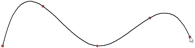
Spline
|
<Shift+H> |
Spline |
The spline is created by successively entering the coordinates of the characteristic points. The points can be specified using ![]() , or you can specify their exact coordinates in the properties window. If the coordinates are specified in the properties window, they should be confirmed by pressing <Enter> or pressing
, or you can specify their exact coordinates in the properties window. If the coordinates are specified in the properties window, they should be confirmed by pressing <Enter> or pressing ![]() in the drawing field. The coordinates of the current point are located at the bottom of the spline parameters tab.
in the drawing field. The coordinates of the current point are located at the bottom of the spline parameters tab.
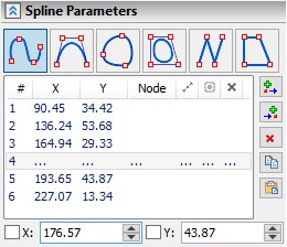
All the characteristic points are consequently displayed on tab of the spline parameters. Their coordinates can be changed. You can add points to the beginning or end of the spline, as well as to any desired place of the spline using the icons If, for example, you need to add a new point between the second and third point, then you can select the coordinates of the second point using |
|
Both in the case of sequential input of points, and when additional points are entered, the change in the geometry of the spline will be dynamically displayed. Variants of the position of the new point will be determined by the position of the cursor. When specifying the characteristic points of the spline, all the usual bindings indicated in the bindings panel are available. Adding points with the help of ![]() and
and ![]() icons, both at the beginning or end of the spline, and in the specified area, the creation of the next new point will be proposed automatically. You can finish inputting new points the same way as completing the input of the spline.
icons, both at the beginning or end of the spline, and in the specified area, the creation of the next new point will be proposed automatically. You can finish inputting new points the same way as completing the input of the spline.
|
|
|
|
Extra spline points can be deleted using ![]() . The coordinates of the selected point can be copied using
. The coordinates of the selected point can be copied using ![]() . The copied coordinates can be passed into another point using
. The copied coordinates can be passed into another point using ![]() .
.
New spline points can be added in the spline editing mode. To do this, just hover cursor over the spline and a dynamic image of a point moving along the spline and following the cursor will appear under the cursor. You should to specify the position of the point on the spline using ![]() .
.
|
<Shift+J> |
Spline by Polyline |
The principle of input of this spline is similar to the input of the usual spline Spline, where you should consequently specify the characteristic points. However, the Spline by Polyline does not pass through the characteristic points. In this type of spline, characteristic points define a polyline along which the spline is constructed.
|
|
|
|
A polyline that defines a spline is indicated by a thin dashed line when creating or editing a spline. The image of characteristic points - as in other lines of a drawing. The position of the current characteristic point coincides with the cursor. The geometry of the spline is changed dynamically according to the position of the point.
The influence of each characteristic point on the spline is determined by the Weight parameter. The point can be suppressed - then the spline will be rearranged in the same way as if the point was removed.
|
|
|
|
A closed spline passing through nodes is constructed using the option:
|
<Shift+K> |
Closed spline |
The principle of a closed spline creation does not differ from the standard spline creation. It is necessary to consistently create characteristic points that will determine the form of a closed curve. The dynamic image of the spline will appear only after entering the coordinates of the second point, since a closed curve can be created at a minimum of three points: Two of the points will be already set by the time the spline is displayed, and the position of the third will correspond to the position of the cursor.
Entering new points on a closed curve will occur in the area between the last and the first characteristic point. If you need to add points in other areas, you can do this by clicking ![]() . Then you should select a point, before which or after which you want to add a new point in the properties window. Then use the icon
. Then you should select a point, before which or after which you want to add a new point in the properties window. Then use the icon ![]() or
or ![]() .
.
|
|
|
|
|
<Shift+L> |
Closed Spline by Polyline |
The principle of entering the characteristic points of a closed spline along a polyline is similar to the principle in the Closed Spline option. As in the Spline by Polyline option, characteristic points define the polyline along which the spline is created, and for each point there is an additional parameter Weight.
|
|
Spline Points Parameters
The parameters of the characteristic points of the normal spline and spline by polyline are different. Only one weight parameter (this parameter has already been described) and the ability to suppress the point are available for the characteristic points of a spline by polyline. As it was already mentioned, if you suppress a point, then it does not affect the creation of the spline, in the same way as if you delete it. The advantage of the Suppress option is that it can be set via a variable.
The parameters of characteristic points of options Spline and Closed spline provide great opportunities in the settings of the mathematical description of the spline.
|
|
1 - manipulator for the length of the tangent vector; 2 - manipulator for the angle of the tangent vector; 3 - manipulator for the radius of curvature.
It is possible to set the following parameters of the point:
●The length of the first derivative (the length of the tangent vector);
●Vector Angle;
●Radius of Curvature;
●Accuracy;
●Suppress Point.
The length of the tangent vector can be set exactly in the properties window, and an approximate value can be set using the manipulator. By default, the length of the tangent vector is given in mm, but the units of measurement can be changed. To do this, click ![]() on the icon
on the icon ![]() of units.
of units.

The manipulator does not show the real length of the tangent vector, because the arrows of the manipulator are adapted to the current scale for convenience. Similarly, you can set the angle of the tangent vector: both with the help of the manipulator and in the properties window. The units of measurement can be changed (by clicking the icon ![]() in the angle input field). By default the angle is measured in degrees [°].
in the angle input field). By default the angle is measured in degrees [°].
The radius of curvature is specified in the same units as the length of the tangent vector. This is because the radius of curvature is a quantity depending on the functions of the spline and its derivatives. Therefore, if the units of measurement are changed in the field of values of the length of the tangent vector, then they will also change in the field of curvature radius. The symbol of the radius of curvature determines the direction of twisting of the spline: “-” sign will be clockwise, “+” sign will be against clockwise.
|
|
|
|
If the length of the tangent vector, the angle or radius of curvature were changed relative to those parameters that were calculated automatically, a flag is placed next to them and the value will be applied. If the flag is removed, the default value will be calculated. |
|
The accuracy sets the maximum possible deviation of the spline from the points defining it. By default, the accuracy value is in mm, but, as is the case with the vector length, the units of measurement may be changed.
In order for an accuracy to be assigned for the selected point, you should enable the flag next to the field. If the accuracy flag is not active, the spline will pass through the point.
If the accuracy is not set, then the system of linear equations is solved for the spline with respect to the specified characteristic points. If you specify tolerance, then the problem with inequality is solved, taking into account the maximum possible given deviation.
Accuracy can be set to those points for which it is necessary, but the accuracy value for all selected points will be the same. If you change the value of the tolerance at one point - it will automatically change for all other points.
For example, for the 2 point of the spline, the accuracy is not active, and for the 3 and 4 it is active (for 1, 5 and 6 points, the tolerance parameter is not active).
|
|
The Suppress option influences the geometry of the spline as if the point was deleted, but if you disable the Suppress flag, the point will again determine the geometry of the spline.
If changes were made in the point parameters, it will be shown in the spline properties window.
|
|
For point number 1 - no additional parameters are specified.
For point number 2 - a fixed value of the radius of curvature is set, if the vector angle of slope or length of the tangent vector were set, the same icon will appear.
For points number 3 and number 4 accuracy is set.
Point number 5 is suppressed.
Point number 6 is bind to the node (you can bind both to the point of a sketch and to the node on a construction line).
Unlike the parameters of points, the general parameters of the spline are the same for both normal splines and polylines. The following spline parameters are available:
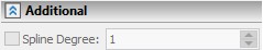
●Spline degree;
●Type of parameterization.
For non-closed splines:
●Start extension;
●End extension.
Spline degree determines the degree of polynomials that describe the spline: polynomials of the first, second, third or fourth degree. By default, splines are built on cubic polynomials. If you specify the degree of the spline equal to one - the spline becomes a polyline.
The Parameterization significantly affects the shape of the spline, especially in areas with closely spaced points that change the direction of the curve.
When changing the type of parameterization, the same parameter value may correspond to a different position on the spline. There will be a different length of the “arc” between two characteristic points of a spline.
The following options for spline parameterization are available: ●By length, ●Centripetal, ●Uniform, ●Local sums, ●Fixed, |
|
By default the Centripetal parameterization is used for splines.
Uniform. The characteristic points Dk, where k = 0,1, ..., n, are set for creation of a spline. The definition domain of the parameters is t [0,1]. The extreme parameters t0 = 0 and t1 = 1. Other parameters 1 / n, 2 / n, ..., (n-1) / n.
With uniform parameterization sharp protuberances, peaks, loops are possible more often than in other methods. At the same time, this type of parameterization is the most simple and intuitive.
By length. Parameters are distributed in accordance with the length of the arcs between adjacent points. The arcs between the points are curves constructed on polynomials, i.e. the spline can be represented as a sequence of such arcs.
The characteristic points Dk, where k = 0,1, ..., n, are set for creation of a spline.
The length of all arcs (spline length) L will be determined by the expression:
![]()
Arc length Lk from D0 to Dk:

The definition domain of the parameters is t [0,1]. Each tk parameter should match the length Lk, then:
t0=0
![]() ,where k=0,1,…,n-1
,where k=0,1,…,n-1
t1=1
The arc length parameterization method is widespread and usually works well. You should take into account that the polynomial spline between two points is not an arc — it can be considered an arc only approximately. If the arc is long, a spline constructed using this type of parameterization can have a great convex.
Centripetal. The name of the method reflects its physical interpretation. When moving along a spline trajectory - the stronger the bend, the greater the centripetal force. The centripetal force is proportional to the angle change. The centripetal parameterization method is an approximation to such a physical model. From the point of view of mathematics, the centripetal method of parameterization is a modification of the method of parameterization by length.
The characteristic points Dk, where k = 0,1, ..., n, are set for creation of a spline. The definition domain of the parameters is t [0,1]. We introduce the exponent α, which will modify the expressions of the method of parameterization by length:
![]()
t0=0
![]() ,where k=0,1,…,n-1
,where k=0,1,…,n-1
t1=1
If α = 1, then the centripetal parameterization and parameterization along the length give the same creation result.
If α˂1 ![]() and
and ![]() , then the influence of a longer arc decreases. Influence means the value of the parameter change for the corresponding arc.
, then the influence of a longer arc decreases. Influence means the value of the parameter change for the corresponding arc.
If α<1 ![]() and
and ![]() , then the influence of a short arc increases.
, then the influence of a short arc increases.
1 - Uniform parameterization 2 - Arc parameterization 3 - Centripetal parameterization |
|
Local sums.
This parameterization method is available for compatibility of splines built in T-FLEX CAD 15 and earlier. When creating splines in T-FLEX CAD 16 it is better to use the three listed above methods.
Fixed. When changing the position of characteristic points or adding points, the parameterization of the spline is recalculated. This is necessary when creating or editing a new spline, therefore, for the spline being built or being edited, the option of fixing the parameterization is disabled. If the spline was split (Split), or trimmed (Trimming) or imported from another system, then it will have a fixed parameterization. In the fixed parameterization mode, spline editing is limited. This is due to the fact that the length of the arc changes upon editing but the parameters values are fixed. When distance between points increases, flat areas can be formed, and when it decreases, loops are formed.
When trimming or splitting a spline, its parameterization type automatically becomes fixed. The type of parameterization for a fixed spline can be changed, but then its geometry will change. In the fixed parameterization mode, it is permissible to make only minor adjustments to the spline.
If the spline is built on three or two points after editing, then changing the parameterization from fixed to any other is not recommended. By default, splines are built on the basis of cubic polynomials, and three points for the correct construction of a cubic spline are not enough. It is necessary either to lower the degree of the spline, or not to change the type of parameterization.
If the spline was split (Split), or trimmed (Trimming), then to save the geometry, the first and second derivatives are fixed at the two extreme points of the spline. If spline editing is necessary, it is recommended to remove the fixation of derivatives.
|
|
Offset allows you to lengthen the spline, or shorten (if you set a negative offset value). If the spline is lengthened, then it is necessary to choose the law of creation of the elongated part of the spline. For this, there are special options in the properties menu that will become available if you set a flag to activate the Start extension and/or End extension.
Let us consider the offset options. Control determines how to set the length of the offset section. If the option By length is selected, then the length is set by the value in the selected units of measurement. If the option By parameter is selected, then the length of the extension region is specified in relative values. The influence of the parameter value on the length of the extension region depends on the type of parameterization of the spline. Negative length and parameter values will shorten the spline. Method of extension determines the law of the construction of the offset region. For negative offsets, the method of elongation does not affect the geometry of the spline. |
|
The following extension methods are available.
●By straight line. With this method, only the first derivative is a smooth function. At the point of the beginning (end) of the spline, a tangent is constructed. Along the tangent, the displacement is calculated. Curvature is not preserved.
●Keep curvature. Both the first and second derivatives are smooth functions. This automatically sets a smooth decrease in curvature to zero. The offset section becomes straight with preservation of curvature.
●Mirror. The spline is reflected symmetrically relative to the line perpendicular to the tangent built at the point of the beginning (end) of the spline.

1 - source spline; 2 - extension section; 3 - tangent at the point of origin; 4 - perpendicular to the tangent
●By parameter. The curvature is preserved; a smooth decrease of the curvature occurs throughout the entire offset section. If the length of the offset section in the selected parameterization method reaches unity, then the curvature is zero and the radius of curvature is infinitely large.
●By arc. Only the first derivative is a smooth function, the curvature is not preserved. A tangent arc of a circle is constructed from the point of the beginning (end) of the spline, whose radius is equal to the radius of curvature at the point of the beginning (end) of the spline.
Smoothness of splines at extreme points
If the extreme point of the spline coincides with the extreme point of another spline or line, then you can specify one of three options for the smoothness of the spline at the point of its transition to another line. The smoothness options are available in the pop-up menu when selecting the extreme point of the spline (provided that the extreme point coincides with the extreme point of another line), as well as in the automenu.
Smooth variations are denoted as G1, G2, G3.

<Shift + 1> G1 - the directions of the tangents coincide in the extreme points of the lines. This means that the angles of the first derivative of the lines at the extreme points will either be equal or differ by a multiple of 180°. For example, let's build two consecutive splines: the last point of the first spline coincides with the first point of the second. For the second spline at the first point, choose the smoothness G1. Now compare the angles of the tangent at the last point of the first spline and the first point of the second. The figure shows that they are equal.
|
|
The last point of the first spline |
The first point of the second spline |
It should be noted that other parameters of the extreme points when using the smoothness of the G1 are different.
The use of G1 smoothness is possible only for splines of the second order and higher.
<Shift + 2> G2 - in the extreme points of the lines the directions of the tangents coincide and the centers of curvature coincide. This means that the equality of the radii of curvature at the extreme points of the curves is added to the condition G1. For example, build an arc with a radius of 35 mm from which is continued by a spline. We indicate the G2 smoothness at the first point of the spline. Now let's look at the radius of curvature at the first point of the spline. It can be seen from the figure that it is equal to 35 mm.


It should be noted that the sign of the radius of curvature reflects the direction of twisting of the spline (this was mentioned above). In addition, if you construct a tangent at the extreme point of the arc, then you can make sure that its direction will coincide with the direction of the tangent of the spline, since the angle of the constructed tangent is equal to the angle of the first derivative at the first point of the spline.

In the case when the spline and the curve to which the extreme point belongs have different twisting directions, the point of sign change (inflection point in the case of continuity) of the curvature function is at the extreme point of the spline. When using G2 smoothness, the inflection point will shift inside the spline, and a bend will be added to the spline itself with the same direction of twist as the curve to which the extreme point belongs. This is necessary to satisfy the condition of coincidence of the centers of the circles of curvature of the lines at the extreme points. Let's give an example. Let two consecutive splines be given. The last section of the first spline is twisted clockwise, the first section of the second is twisted in the opposite direction. We derive the curvature for these splines using the Show Curvature command (this command will be discussed in more detail in the next subsection).

It can be seen from the figure that the curvature function changes sign at the last point of the first spline and the first point of the second spline, and in this case with the function breaking.
Apply the smoothness of G2 to the last point of the first spline. It can be seen from the figure that the inflection point has shifted into the first spline: a small section was added to the first spline with a twisting direction corresponding to the direction of the second spline.

It should be noted that the curvature function became continuous, but at the extreme points the smoothness of the curvature function is broken. To maintain the smoothness of the curvature function at the extreme points of the spline, there is a third version of smoothness.
The use of G2 smoothness is possible only for splines of the third degree and higher.
<Shift + 3> G3 - in the extreme points of the lines the directions of the tangents coincide, the curvature centers coincide and the directions of the tangents to the curvature function coincide. This means that the condition for the smoothness of the curvature function is added to the conditions G1 and G2. We continue the previous example with two consecutive splines. For the extreme point of the first spline, instead of the smoothness of G2, we choose the smoothness of G3. It can be seen from the figure that when using G3 smoothness, the curvature function preserves smoothness at the extreme points of the splines.
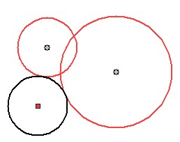
The use of G3 smoothness is possible only for splines of the fourth degree and higher. If the spline has a lower order than the fourth, then when you select the smoothness of the G3, the degree of the spline will be automatically increased to the fourth.
If we consider the smoothness of G1, G2, G3 from the point of view of their influence on the curvature function, then we can formulate the following rule:
G1 - the curvature function does not preserve continuity at the extreme points;
G2 - the curvature function is continuous, but does not preserve smoothness at the extreme points;
G3 - the curvature function is continuous and retains smoothness at the extreme points.
|
|
|
G1 |
G2 |
G3 |
A variant of the smoothness of the extreme points can be seen in the properties window of the spline.

The tangent angle at the extreme point can be changed by 180°. For this, in the pop-up menu and automenu of the extreme points of the spline, in addition to the options for smoothness, there is also the command <Shift + 4> Reverse Tangent Direction.
|
|
Spline Analysis
For the analysis of the geometry of the splines, there are two main tools: curvature of curves and radius of curvature. Curvature - the reciprocal of the radius of curvature. Curvature allows you to check the smoothness of the spline: preservation of curvature (smoothness of the second derivative).
Call the command to measure the curvature through the context menu. The context menu is invoked by clicking ![]() on the spline. Then click
on the spline. Then click ![]() on the icon
on the icon ![]() and call the Show Curvature command. This command can also be invoked via a Ribbon or text menu.
and call the Show Curvature command. This command can also be invoked via a Ribbon or text menu.
Keyboard |
Ribbon |
|---|---|
<QC> |
Measurement → Curvature |
Icon |
Textual Menu |
|
Service> Geometry Analysis> Curvature |
If the option is not called through the context menu, then you need to select the spline by clicking ![]() .
.
In the Show curvature option, you can change the displayed value from curvature to radius of curvature by activating the corresponding switch. The graphic output of the radius of curvature will be in millimeters. |
|
The graphic output of curvature will be determined by the formula:
![]()
In the properties window, for convenience of curvature analysis, you can change the scale. The radius of curvature is always graphically displayed in real scale.
It is possible to show points with maximum curvature and points of bends: To do this, you need to set the appropriate flags in the properties window. |
|
Curvature measurement helps to understand the difference in the law of construction of offsets for a spline. Some of them allow to preserve the smoothness of the second derivative (curvature), some - only the first (tangent).
The arc offset is the first derivative of a smooth function, the second (curvature) has a break. |
|
Parameter offset - curvature without kinks, a smooth decrease in curvature. |
|
The Show Curvature command has the option to measure curvature values at any point.
Keyboard |
Ribbon |
|---|---|
<QC>→<C> |
Measurement → Curvature → Measure curvature at arbitrary point |
Icon |
Textual Menu |
|
Tools> Geometry Analysis> Curvature> Measure curvature at arbitrary point |
When you call this option on the spline (as on any other line), a dynamically moving point will appear. Clicking ![]() at the point under the cursor will measure the curvature and radius of curvature. The radius of curvature will be in meters, the curvature is the reciprocal of the radius of curvature in meters.
at the point under the cursor will measure the curvature and radius of curvature. The radius of curvature will be in meters, the curvature is the reciprocal of the radius of curvature in meters.

|
<Shift+G> |
Polyline |
|
<Shift+F> |
Closed Polyline |
As mentioned above, the polyline is a spline of the first degree. The principle of constructing, editing and adding new points is similar to the spline. For polylines, there are no additional spline parameters and no point parameters. Point can only be suppressed.
Visually, when creating a polyline, we get consecutive segments. However, the interrelations of these segments is different than if we would draw segments in a coherent sketching mode or parametric segments (with constraint). In contrast to the specified options, a broken polyline is a single object.
For example, parts of a polyline cannot be rounded together, and when a segment is deleted, the deleted part will consist of a set of segments. You can create an offset curve to the polyline.
|
|
The commands for chamfering and rounding in the auto-menu are combined into one list. In the automenu list is called when you hold the fillet or chamfer icon. When working with these commands, the list will be hidden under that icon, the command of which was called last.

In the Ribbon, chamfering and fillet are caused by separate icons that are not combined into a list.

When constructing chamfers and fillets, the existing graphic lines are modified, and new ones are formed. Select two lines and specify the chamfer or fillet parameters to create chamfers and fillets. In this case, the chamfer can be constructed only for straight intersecting lines. The rounding can be constructed for any lines.
Fillet
Keyboard |
Ribbon |
|---|---|
<SK>→<Shift+B> |
Drawing → Sketch → Fillet |
Icon |
Textual Menu |
|
Design> Sketch> Fillet/Chamfer |
You can round any corner: straight, obtuse, sharp.

Also, using the Fillet command, you can create tangent arcs of a given radius between sketch lines that do not intersect.

It is necessary to select two lines successively to create fillet: you should select the first with the help of ![]() and place the cursor on the second. All variants of the position of tangential arcs of the specified radius that can be constructed between the selected lines will be automatically determined: they are shown in dotted lines. At the same time, the current fillet option is displayed by a thickened blue line of the drawing. The first proposed rounding variant depends on the position of the cursor when selecting a line. You can change the position of the fillet arc by moving the cursor, or you can use the <Z> key.
and place the cursor on the second. All variants of the position of tangential arcs of the specified radius that can be constructed between the selected lines will be automatically determined: they are shown in dotted lines. At the same time, the current fillet option is displayed by a thickened blue line of the drawing. The first proposed rounding variant depends on the position of the cursor when selecting a line. You can change the position of the fillet arc by moving the cursor, or you can use the <Z> key.
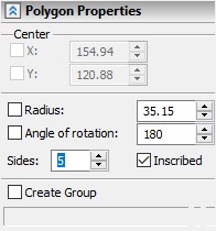
You can also change the way of tangency to the arc with the <R> key.

You can build the current rounding option using the ![]() or <Enter> key.
or <Enter> key.
The thickened blue line defines the geometry of the sketch line to be created. The original lines are highlighted in red. Source lines can be trimmed: To do this, you should specify the appropriate flag in the properties window (by default, trimming lines is enabled). If the option flag is cleared, the original lines will remain unchanged. In the properties window you should also specify the radius of the rounding.


If the rounding radius cannot be built for the selected lines, a corresponding warning will be displayed.
After constructing the rounding radius, the resulting line will be an arc. You can change the rounding radius only with the parameters available for the arc.
Keyboard |
Ribbon |
|---|---|
<SK>→<Ctrl+B> |
Drawing → Sketch → Chamfer |
Icon |
Textual Menu |
|
Design> Sketch> Fillet/Chamfer |
In addition, as in the fillet command, a chamfer can be constructed between segments that intersect at a right, obtuse or sharp angle.
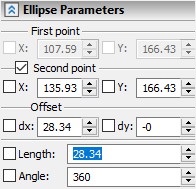
In addition, as in the fillet command, when the intersection of the segments is not at the point of their beginning or end, there are four options for constructing a chamfer. To select the desired variant of chamfer construction, it is necessary to select segments in the place where it is planned to create a chamfer. Lines beyond the chamfer can be trimmed or not trimmed, which is indicated by the corresponding flag in the command properties window (by default, trimming of protruding lines is active).

If the lines do not intersect or the size of the chamfer is too large for the selected segments, then the chamfer cannot be built and a warning will be displayed.
After the chamfer is created, the line will become a segment. When editing a chamfer line, only segment parameters will be available.
Three options for defining geometry are available in the chamfering command:
●Symmetrical chamfer ![]()
●Chamfer by offset ![]()
●Chamfer by angle and offset ![]()
To select the desired type of chamfer in the properties window, click on one of the three icons. The default is symmetrical chamfer. The selected type of chamfer changes the geometric parameters that must be specified for its construction.
This command is used to create a line that is offset to a specified distance relative to the group of conjugate graphic line. The group of lines can include segments, circular arcs, and splines. In addition, segments and arcs obtained by rounding and chamfering options can be included. The main condition is that the lines should be a continuous sequence: the end of one line must correspond to the beginning of the next.
Keyboard |
Ribbon |
|---|---|
<SK>→<Ctrl+J> |
Drawing → Sketch → Offset |
Icon |
Textual Menu |
|
Drawing> Sketch> Offset of a group of graphic lines |
The lines from which the offset curve is constructed can be either smoothly conjugated or not (1 - spline; 2 - arc; 3 - segment).
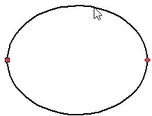
It is possible to construct an offset curve from a closed contour (3 - segment; 4 - arc obtained by fillet; 5 - segment obtained by chamfer). If the Sequence selection flag is set to create an offset curve, it is enough to specify at least one line from a continuous sequence using If the sequence selection mode is disabled, each line must be manually selected using |
|
The Copy Style flag allows you to transfer the properties of source lines (type, thickness, color, etc.) to the offset curve. Setting the Round corners flag will result in an automatic rounding of the kinks of the created curve (6 - offset curve with copying style; 7 - offset curve with corner rounding).

The option Consider self-intersections - cuts off parts of the curve behind the intersection point, leaving only a closed contour.
In the process of creating an offset curve, a dynamic image of the created curve will be attached to the cursor. The position of the offset curve can be set arbitrarily with ![]() or precisely by specifying the exact offset value in the properties window.
or precisely by specifying the exact offset value in the properties window.
In order to construct center lines for such elements as an arc, a circle and an ellipse, you need to select the appropriate command.
Keyboard |
Ribbon |
|---|---|
<SK>→<Ctrl+Q> |
Drawing → Sketch → Axis lines |
Icon |
Textual Menu |
|
Drawing> Sketch> Axis lines |
After that, it is enough to choose any of the specified lines on the drawing with the help of ![]() , and the axial ones will be created automatically.
, and the axial ones will be created automatically.

If the line for which the centerline was constructed was edited, the axial lines will not be rebuilt automatically, they will also need to be edited or re-created.
Methods for Modifying Graphic Lines
Modification of lengthening and shortening can be used to edit segments of arcs and splines.
Keyboard |
Ribbon |
|---|---|
<SK>→<Ctrl+I> |
Design → Sketch → Extend |
Icon |
Textual Menu |
|
Design> Sketch> Extend graphic line |
You need to choose a graphic line that you want to extend or shorten with the help of ![]() . The selected item and possible options for its change will be highlighted: if it is an arc, then a fixed circle will appear, if it is a spline then a fixed line of the spline will appear. In this case, a spline at the first editing can only be shortened, since beyond the spline line the position of the points is not defined. To extend a spline, there is a special option Offset available when creating a spline (the description of this option is given in the subsection “Spline Parameters”). When selecting a segment, no additional lines appear.
. The selected item and possible options for its change will be highlighted: if it is an arc, then a fixed circle will appear, if it is a spline then a fixed line of the spline will appear. In this case, a spline at the first editing can only be shortened, since beyond the spline line the position of the points is not defined. To extend a spline, there is a special option Offset available when creating a spline (the description of this option is given in the subsection “Spline Parameters”). When selecting a segment, no additional lines appear.
The editable element will be displayed in red before the change. Also, the extreme node of the selected element is highlighted. It is the one to which the cursor was closest to the moment of selection. This node can be moved along the displayed fixed line with the help of the cursor (or simply along a straight line, if a segment is selected). It is possible to fix the position of the node, and, therefore, the new display of the element using ![]() . You can also select a sketch line with which you want to intersect by lengthen or shorten the edited element.
. You can also select a sketch line with which you want to intersect by lengthen or shorten the edited element.

The geometry of the modified spline after using the extension and shorten commands will be determined along the entire original line of the spline. After applying the considered command, the line of the spline can be edited, including the part that is invisible after shortening. The invisible part will be displayed as a thin dashed line. Editing such a dashed line can affect the geometry of the visible part of the spline. In the case of spline extension, the fixed line, along which the node bounding the visible line moves, also changes.
You can trim (remove part of the sketch line) any sketch line: a segment (including center lines), a circle, an arc, an ellipse, or a spline.
Keyboard |
Ribbon |
|---|---|
<SK>→<Shift+I> |
Drawing → Sketch → Trim |
Icon |
Textual Menu |
|
Design> Sketch> Trim Graphic Lines |
In order to trim a graphic line you need to select a section to be deleted using ![]() in the Trim command mode. The selected area can be bounded on one or two sides by any graphic line (if you choose a line that is not limited by anything, it will be removed completely). If the free end of the line was chosen, it will be trimmed by the nearest intersecting line. If the selected line is limited by two intersections, then the part of the line between intersections will be removed.
in the Trim command mode. The selected area can be bounded on one or two sides by any graphic line (if you choose a line that is not limited by anything, it will be removed completely). If the free end of the line was chosen, it will be trimmed by the nearest intersecting line. If the selected line is limited by two intersections, then the part of the line between intersections will be removed.
|
|
|
|
|
|
When trimming a spline line on a spline, new characteristic points appear, created at the intersection of the spline with its bounding lines during trimming. Behind the points, the spline is not defined by anything, i.e. unlike the Extend/Shorten command, there are no invisible lines defining its geometry outside the visible line of the spline. Since new characteristic points determine the geometry of the spline, after the trimming operation, then you can adjust the spline by changing their position.
Commands combined in one drop-down menu are used to split existing graphic lines into several parts. Both in the Ribbon and in the automenu the commands are grouped in the same way. |
|
Keyboard |
Ribbon |
|---|---|
<SK>→< Ctrl+K > |
Drawing → Sketch → Split |
Icon |
Textual Menu |
|
Design> Sketch> Split graphic line |
The Split command allows you to split an existing graphic line into two at a specified point. To do this, press ![]() to select the graphic line. It will be highlighted and a dynamically moved image of the point dividing the element into two parts will appear on it. After pressing
to select the graphic line. It will be highlighted and a dynamically moved image of the point dividing the element into two parts will appear on it. After pressing ![]() , the point is fixed and the line is divided into two. The point can also be specified as the point of intersection of the selected element with any other graphic line (line segment, circle, arc, and spline). To do this, select the graphic line, the point of intersection with which will be the splitting point of the variable element.
, the point is fixed and the line is divided into two. The point can also be specified as the point of intersection of the selected element with any other graphic line (line segment, circle, arc, and spline). To do this, select the graphic line, the point of intersection with which will be the splitting point of the variable element.
When a command is executed, two characteristic points are created in the specified place: each of which belongs to two new lines.

If the line is closed, for example, a circle, an ellipse, or a closed spline, then you need to specify two split points.
To split a line into an arbitrary number of equal parts, use the command:
Keyboard |
Ribbon |
|---|---|
<SK>→< Ctrl+L > |
Drawing → Sketch → Split into ‘n’ parts |
Icon |
Textual Menu |
|
Design> Sketch> Split into ‘n’ parts |
After calling the command, you need to press ![]() to specify the line you want to break. If you select a closed line (circle, ellipse, closed spline), you must additionally specify the starting point of the split.
to specify the line you want to break. If you select a closed line (circle, ellipse, closed spline), you must additionally specify the starting point of the split.
|
|
As a result, the selected line is divided into a specified number of equal parts. The resulting lines are not connected to each other and can be edited separately.
The number of parts into which the line will be broken is set in the properties window.

Any graphic line can be displayed symmetrically: segments (including those obtained by the Chamfer option or when constructing rectangles and polygons), arcs (including those obtained by the Fillet option), circles, ellipses, splines, offset lines, axial lines (including those obtained in the Axial mode), and all lines obtained after modification.
Icon |
Ribbon |
|---|---|
|
Design → Sketch → Symmetry |
For example, we will have a sketch containing all of the above sketch lines. To perform symmetry, it is necessary to select the lines that need to be symmetrically copied. You may select lines first and call Symmetry command. Other way you may call the command and then select required lines. In the second case, you will need to confirm the selection (the key combination <Ctrl + Enter>). The choice of lines is carried out in the usual way using ![]() with pressed <Shift> if you need to select several lines.
with pressed <Shift> if you need to select several lines.
Holding |
|
After the necessary lines have been selected and confirmed (<Ctrl + Enter>), two points should be set on the drawing that define the line of symmetry. You can set them using ![]() , or you can enter the exact coordinates in the properties window. When selecting points, all standard bindings are enabled. When a second point is selected in dynamic mode, the position of the symmetrically displayed lines will be shown.
, or you can enter the exact coordinates in the properties window. When selecting points, all standard bindings are enabled. When a second point is selected in dynamic mode, the position of the symmetrically displayed lines will be shown.
|
|
See also: Sketch Editing, Creating a Sketch with Constraints