Selecting LCS for 2D Elements Creation |
  
|
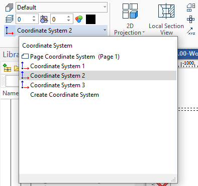
By default, all drawing elements are created in the page coordinate system (CS). You can select a different CS in the list of a drawing coordinate systems. The list can be found in the Ribbon in the Style group near the icon for a user CS creation. All coordinate systems for the current page and workplane are displayed in the list.
Icon |
Ribbon |
|---|---|
|
Draw > Style > Coordinate System Assembly (2D) > Style > Coordinate System Sheet Metal (2D) > Style > Coordinate System Remarks > Style > Coordinate System Workplane > Style > Coordinate System |
Keyboard |
Textual Menu |
|
|

The active CS is shown in the Ribbon. On the page or workplane it will be displayed with thick lines.
You can call a user CS creation in the bottom of the list.
The selected CS will determine coordinates of the created constructions. The selected CS determines constructions only on the current page or workplane like the default CS. The created CS will not be available on other pages or workplanes.
User CS is not displayed in the hidden construction lines mode, is not printed and is not exported to third-party formats.
Changes of a user CS location will cause position changes for all constructions created according to this CS.