2D Local Coordinate System |
  
|
Using the following command, you can create a custom coordinate system, in order to use it later, when creating other 2D elements:
Icon |
Ribbon |
|---|---|
|
Draw > Style > LCS Assembly (2D) > Style > LCS Sheet Metal (2D) > Style > LCS Remarks > Style > LCS Workplane > Style > LCS |
Keyboard |
Textual Menu |
|
|
Upon calling the command, you can anytime switch between creation of fixing vectors, 2D coordinate systems and 2D connectors using the following automenu options:
|
<F> |
|
|
<L> |
Create LCS |
|
<C> |
Following options are also available:
|
<Ctrl>+<Enter> |
Create fixing vector by one point (Finish Input) |
|
<N> |
Select Node |
|
<F4> |
(Edit fixing vector, 2D LCS or 2D connector) |
|
<Esc> |
Exit command |
Creating LCS
In order to create an LCS, upon calling the command, specify two nodes, which define its OX axis. Selection is performed by moving the cursor over the desired point and pressing ![]() or <Enter>. The first selected node will be the origin of the LCS. The second node will determine the direction of the OX axis. The OY axis is perpendicular to the OX axis. You may edit point later to change the CS position and orientation.
or <Enter>. The first selected node will be the origin of the LCS. The second node will determine the direction of the OX axis. The OY axis is perpendicular to the OX axis. You may edit point later to change the CS position and orientation.
You can use arbitrary point of a drawing, or select existing 2D nodes, characteristic points of graphic lines and intersections of construction lines using object snappings. Selecting a characteristic point of a graphic line or an intersection of construction lines results in automatic creation of a connected 2D node there. The following automenu option can be used for selecting existing 2D nodes:
|
<N> |
Select Node |
Upon activating this option, pressing ![]() anywhere within drawing window results in selecting a nearest existing 2D node.
anywhere within drawing window results in selecting a nearest existing 2D node.
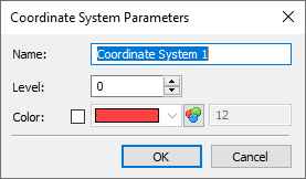
Upon specifying two points, the LCS parameters dialog appears.
A dialog for the CS creation will appear after two nodes selection.

You can specify Level, Color and Name for the CS.
The created CS is not an active CS that defines coordinates of the created drawing elements. You should select it before constructions creation to make the CS active.