Levels |
  
|
Command call:
Icon |
Ribbon |
|---|---|
|
3D Model > Style > Levels Draw > Style > Levels Assembly > Style > Levels Sheet Metal > Style > Levels Surfaces > Style > Levels Weld > Style > Levels Routing > Style > Levels Primitives > Style > Levels Support Geometry > Style > Levels Edit > Document > levels Remarks > Style > Levels Workplane > Style > Levels |
Keyboard |
Textual Menu |
<SH> |
Customize > Levels |
When using the textual interface, the command is available in the System toolbar.
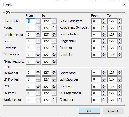
The Levels command allows you to set the visibility intervals of graphic items.
Each graphic element of the system has a level. Element level is an integer that determines the visibility of the element when redrawing. You can set the level of an element in the range from -126 to 127. The visibility of each element depends on the interval specified in the Levels command. You can set the interval of visibility using two numbers (from -126 to 127) for various types of elements.
The visibility of elements is determined as follows:
If the first number is less than or equal to the second, then only those elements are displayed whose level value falls within this interval (including the boundaries of the interval).
If the first number is greater than the second, then only those elements are visible whose level values do not fall within the specified interval (from the lowest value to the highest, excluding the borders).
If you want to remove particular elements from the drawing, set the visibility interval for them so, that the level of these elements does not fall into it. By default, a value for the Level parameter for each element is equal to 0.

An interesting thing is the possibility of defining visibility intervals via variables. This allows, depending on some calculations or conditions, to display or hide elements of particular types.
Topics in this section: