Drawing Techniques |
  
|
A T-FLEX CAD drawing can be created in one of the following ways:
Parametric Drawing
This is the recommended drawing technique in T-FLEX CAD. Take the advantage of parametric design capabilities of T-FLEX CAD to create a drawing, that can be easily modified according to your design intent. Such a drawing can also be added to a parametric model library to be later used in other, more complex drawings. In the latter case, one can specify a new location for the drawing as a fragment, and modify parameters to obtain a necessary shape.
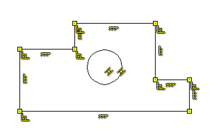
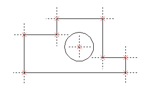
Non-parametric Drawing (Sketch)
This is a conventional drawing similar to those created by most CAD systems. This drawing is created by using the standard set of functions for drawing different basic elements (straight lines, arcs, circles, ellipses, splines etc.) and by using the mechanism of objects snaps. These drawings do not have advantages of parametric drawings, as far as efficient modification of parameters (dimensions) is concerned, however, in certain cases creating these drawings saves time and can give the benefit, when significant subsequent modification is not required.
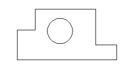
Creating Parametric Drawing in T-FLEX CAD
In T-FLEX CAD, there are two ways to create a parametric drawing: using the Sketch and Constrains commands, or based on construction lines.
The first method is based on the mechanism of variational parametrization, i.e. geometric and dimensional dependencies are created directly on the image lines. The second method is based on the history of constructions, i.e. the user independently determines the geometric dependencies between the lines of construction, and then based on these elements builds the image lines of the drawing.
Parametrization by History of Constructions |
Variational Parametrization (Sketch) |
The position of the geometric element relative to previously constructed elements is determined, when it is created. |
The position of the geometric element can be set or changed at any time using constraints. |
Cyclic dependencies are not possible (previously constructed elements cannot depend on elements constructed later) |
Cyclic dependencies are possible |
The parametric model is always completely and uniquely defined |
The model may not be fully defined, which, on the one hand, makes it convenient to modify it, but on the other, it can lead to unpredictable results upon parametric changes |
Recalculation of the model requires only a single pass, which allows you to quickly read models with a large number of elements |
Recalculation of the model requires specialized calculation of the constraint system, which limits the dimension of the model and the speed of calculations |
Uses construction elements, on the basis of which image lines are created. |
It does not require the use of construction lines. Dependencies are imposed through constraints and driving dimensions. |
Variables are used, when setting parameters of construction elements. |
Variables are used as values of driving dimensions, as well as to suppress constraints and driving dimensions in order to qualitatively change the parametrization scheme |
Overriding dependencies between elements is rather complicated, sometimes impossible process |
Overriding dependencies between elements comes down to removing constraints and creating new constraints |
Automatically detecting dependencies and establishing relationships between elements is difficult |
It is possible to automatically identify relationships and create constraints both, when creating model elements, and for previously created elements, for example, for imported drawings and sketches |
Briefly consider each of these methods.
Creating a drawing with Variational Parametrization (Sketch with Constraints)
A drawing is created using the Sketch command in the automatic constraint creation mode.

In the process of creating image lines, the system itself establishes the dependencies between the elements. Constraints allow you to change the geometry of models, establishing relationships between the lines of the drawing. Driving dimensions allow you to quickly and clearly change the created drawing. Driving dimensions can be created manually or in automatic mode.

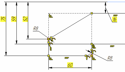
Creating a Parametric Drawing based on Constructions
Creating a drawing in T-FLEX CAD begins with creating construction elements. Construction elements can be created by various means. First, create the base construction lines, that will be used as a reference for additional construction lines. The base lines can be vertical or horizontal. Next, create straight lines and circles dependent on the base lines. For instance, construct parallel lines, tangent circles, etc. The way in which additional lines are created is stored in the model. The line intersections provide reference locations for nodes, that need to be created for further construction.
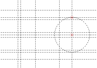
More straight lines and circles can then be created referencing the earlier ones in various ways. A line, for instance, can be created through two nodes; a circle can be drawn through a node and tangent to a line. All these construction steps are stored, and in future the thus created entities will be adjusting to the base and other elements' modifications according to their creation history.
Thus, the early stage of creating a drawing involves building parametric dependencies among construction elements, that become the parametric framework of the drawing. Once the construction framework is built, proceed with drawing the graphic elements. Create line segments, arcs and circles by drawing over the construction lines, snapping to nodes.
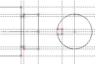
Once the actual drawing graphics is complete, proceed with the drawing detailing. Create dimensions referencing construction lines and nodes. Define hatch contours, their filling patterns and other particulars. Add texts. When placing text, use snapping to nodes and construction lines if necessary. This would be necessary, if a text is supposed to move together with the drawing lines. Further, define GD&T symbols, roughness's and leader notes.
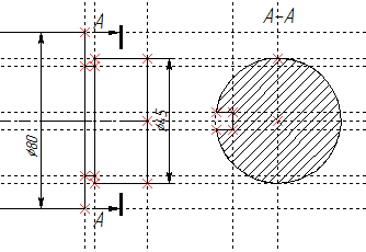
Finally, a complete parametric drawing is created and can further be modified. You can modify parameters of construction elements, such as distances between parallel lines, angles between lines, radii of circles.
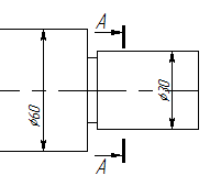
The graphic elements will subsequently adjust with the construction ones they reference. Thus, a family of variations of the original drawing can be created. All the rest of the drawing layout will also adjust accordingly.
Construction elements may have a numerical parameter (offset from parallel line, angle, radius, etc.). Parameter's value is defined during element's creation. Some of the construction elements do not have such parameters, e.g.: a line passing through two nodes. A variable can be used as a parameter's value. Variable may be defined by a constant value or by an expression. Expression may contain other variables, various arithmetical and logical operations, conditions, standard mathematical functions, database queries.
Any T-FLEX CAD drawing may be used as a fragment with customizable parameters within other drawing. Fragments can be used for creating parametric 2D assemblies.
Creating a Non-Parametric Drawing (Sketch without Constraints)
This technique implies quick sketching of the drawing graphics, completely avoiding preliminary creation of the construction elements. Sketching supports object snapping and provides dynamic hints, that make the drawing process simple and slick. However, thus created drawings do not share the parametric drawings' capability of parameters' (dimensions') modifications. Creating non-parametric drawings may be somewhat preferable in cases, when no significant modifications are expected.
Topics in this section:
•Examples of Drawings Creation
•Move, Copy, Arrays of 2D Elements
•Copy 2D Elements with Clipboard
•Grid