Constraints |
  
|
Constraints |
|
The command can be called in one of the following ways:
Icon |
Ribbon |
|---|---|
|
Draw > Constraints > Constraint Workplane > Constraints > Constraint |
Keyboard |
Textual Menu |
<SC> |
Draw > Constraint |
The command allows to create constraints, i.e. geometrical relations between sketch lines.
The number of drawing's Degrees of Freedom, the checkbox allowing to Show Under Defined Lines and control for selecting the Color of under-defined lines highlighting are located in the upper section command's parameters window (see the Graphic Lines' Degrees of Freedom section).
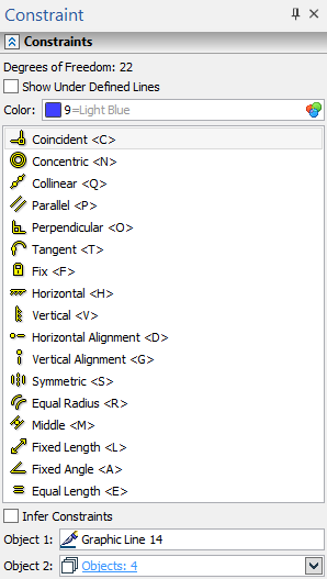
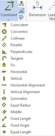
Upon calling the command, you have to select a type of constraint to be created. Click ![]() a desired type in the list in the parameters window or use its hot key. Alternatively you can select a type of constraint directly in the ribbon. Selecting a type in the ribbon launches the Constraint command with the corresponding type pre-selected.
a desired type in the list in the parameters window or use its hot key. Alternatively you can select a type of constraint directly in the ribbon. Selecting a type in the ribbon launches the Constraint command with the corresponding type pre-selected.
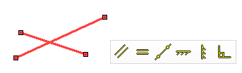
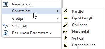
Moreover, upon selecting multiple graphic lines in a drawing window, applicable constraint types can be selected in the dynamic toolbar and contextual menu.
Upon selecting a type of constraint, you have to sequentially select elements to be constrained by clicking ![]() them in the drawing window. Names and icons of selected elements are displayed in the Object 1, Object 2, Object 3 boxes below the list of constraint types. The number of boxes, and, therefore, the number of elements to be selected depends on the type of constraint. Some boxes allow selection of several elements. Such boxes are collapsed
them in the drawing window. Names and icons of selected elements are displayed in the Object 1, Object 2, Object 3 boxes below the list of constraint types. The number of boxes, and, therefore, the number of elements to be selected depends on the type of constraint. Some boxes allow selection of several elements. Such boxes are collapsed ![]() by default, so you can only see the number of selected elements. You can Expand
by default, so you can only see the number of selected elements. You can Expand ![]() a box using the button located in the right side of the box.
a box using the button located in the right side of the box.
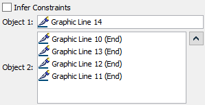
Also, there is the Infer Constraints checkbox below the list of constraint types. It's disabled by default, so you have to finish input using ![]() or <Ctrl>+<Enter>, in order to create a constraint. If the checkbox is enabled, the constraints are created instantly, upon selecting a minimal required number of elements, without the need to finishing the input. Then the system proceed to selection of elements for the next constraint of the same type.
or <Ctrl>+<Enter>, in order to create a constraint. If the checkbox is enabled, the constraints are created instantly, upon selecting a minimal required number of elements, without the need to finishing the input. Then the system proceed to selection of elements for the next constraint of the same type.
Other methods of creating constraints
The Constraint command is used for manual creation of single constraints. Instead, you can create constraints automatically. Within the sketch commands you can use the Infer constraints mode for automatic constraining of lines during their creation. In order to create constraints automatically for already existing lines, use the Find and Infer Constraints command.
In addition to constraints, you can use driving dimensions to parametrize a sketch.
Working with constraints
When creating constraints, there is no hierarchy in the sequence of selecting graphic lines and points. To fulfill the constraint, the whole line or only its characteristic point can move (moving a characteristic point changes a geometry of a line); the first selected element and the second one can move. This is connected with the very idea of variable parametrization, when the entire set of possible geometrical positions corresponds to each interrelation (constraint) of elements. To specify all interrelations between lines, geometry of lines and their position on a plane, you need to specify the required number of constraints and driving dimensions.
If construction lines are used for creation of the drawing, it is necessary to remember, that they have priority. When editing a drawing, the construction lines will act as constants, relative to which the sketch will be parametrically rearranged. In this case, the parametrization of the construction lines themselves will be preserved, having priority over the lines of the sketch.
As a result, the following rule should be used.
You can snap sketch lines to construction lines, but you cannot snap construction lines to sketch lines.
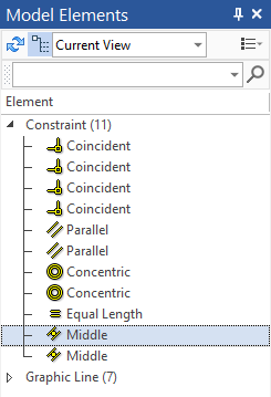
The created constraints can be seen as in the drawing as well as in the Model Elements window. They are displayed with icons similar to icons used in the Ribbon. The icons in the drawing are located next to those points and lines to which the corresponding limiting relationships are applied. In the Model Elements window, you can select any constraint, then the drawing will highlight those lines and points to which this constraint is imposed, as well as the icon for this constraint. A similar highlight will appear if you move the cursor over a constraint icon in the drawing window.
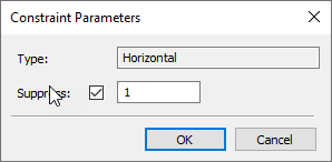
For any constraint, you can call its parameters dialog by clicking ![]()
![]() a constraint in the Model Elements window or in the drawing window. The window indicates the type of the constraint and contains the Suppress checkbox. Enabling the checkbox excludes the constraint from sketch calculation. You can also control the Suppress checkbox via variable, by typing its name into the input box located near the checkbox. Enabled checkbox corresponds to the 1 value, disabled - 0. Any value above 1 or below -1 inclusive gets replaced by the 1. Any value between -1 and 1 gets replaced by the 0.
a constraint in the Model Elements window or in the drawing window. The window indicates the type of the constraint and contains the Suppress checkbox. Enabling the checkbox excludes the constraint from sketch calculation. You can also control the Suppress checkbox via variable, by typing its name into the input box located near the checkbox. Enabled checkbox corresponds to the 1 value, disabled - 0. Any value above 1 or below -1 inclusive gets replaced by the 1. Any value between -1 and 1 gets replaced by the 0.
You can also suppress the constraint through the contextual menu.
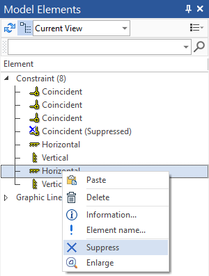
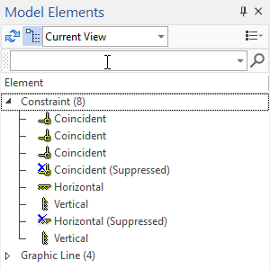
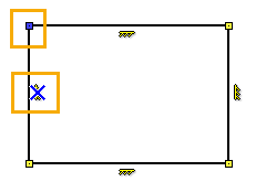
If a constraint is suppressed, then a blue cross is displayed over its icon in the Model Elements window. The same cross is displayed in the drawing window for all suppressed constraints, excepth the Coincidence. Suppressing a coincidence constraint makes its icon blue in drawing window.
Topics in this section: