Graphic Lines' Degrees of Freedom |
  
|
Constraints specify the absolute and relative position of the drawing lines in the drawing. In other words, they limit the degrees of freedom of graphic lines and their characteristic points. The number of degrees of freedom of the drawing can be viewed in the parameters window, when invoking any constraint creation command. The number of degrees of freedom defines the number of translation options for all lines in the drawing. For example, if you draw a straight line segment, then it will have four degrees of freedom: we can change its length, move it vertically or horizontally and rotate. Or, from other point of view, segment's end points have two degrees of freedom. If you fix one point, then there will be 2 degrees of freedom for the segment: only one point will have 2 degrees of freedom, i.e. the segment can only be rotated and its length changed. If, in addition to fixing the point, you fix the length of the segment, then only a single degree of freedom remains - rotation of a segment or moving a point along a circle.
If you draw a circle, then it will have 3 three degrees of freedom: moving vertically and horizontally, as well as changing the radius. If segment and circle are both in the drawing, there will be 7 degrees of freedom in total.
The parameters window always displays the total number of degrees of freedom of the drawing, taking into account the constraints created.
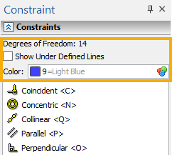
To understand, which graphic lines still have degrees of freedom, there is the special checkbox in the parameters window of constraints creation command - Show under defined lines. Upon enabling the checkbox, all graphic lines that have at least one degree of freedom will be highlighted on the drawing with the color set in the Color box (blue by default) .
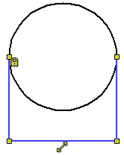
The status of drawing's degrees of freedom can be easily detected by the color of control dimensions background and the color of the Coincidence constraints.
Following colors are used by default:
•Yellow - the drawing is under-defined, i.e. has degrees of freedom
•Green - the drawing is fully defined, i.e. has no degrees of freedom.
•Red - the drawing is over-defined, i.e. there are dimensions or constraints duplicating or conflicting each other.
The colors can be customized in the system options (Options > Colors > Constraints).
When creating parametric models, it is extremely important to fully define the sketch. When changing driving parameters, all under defined lines will be rearranged randomly.
|
|
|
Under-defined sketch |
Fully defined sketch |
Over-defined sketch |
Another important point in the parametrization of the sketch with the help of constraints and control dimensions is the fixating of the direction of the driving dimensions.
If a driving dimension specifies the distance between the lines, which can change their position in result of the parametrization, then it is necessary to fix the direction of the driving dimension.
Otherwise, the relative position of the elements after rebuilding can be reversed.
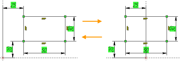
Fixating the direction of a driving dimension can be done via enabling the Fix Direction checkbox in dimension's contextual menu. Also, there you can Change Direction to an opposite one.
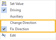
Example
Under-Defined, Fully Defined and Over-Defined Drawings
Let's explore the simple drawing is shown in the figure below. There are no constraints and driving dimensions, i.e. drawing lines have no parametric relations. With the help of constraints and driving dimensions we will make the drawing parametric and fully defined.
The drawing has 20 degrees of freedom. The number of degrees of freedom of the drawing is displayed in the parameters window of the Constraint command. Let's make a Tangent constraint between all segments, tangent to a circle and arc.
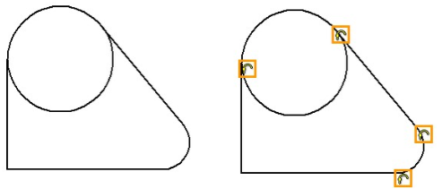
The number of degrees of freedom decreased to 16. Next, connect all the end points of the successive lines of the drawing to each other by the Coincidence constraint. For segments tangent to a circle, the coincidence will be between the end points of the segments and the circle line, but not between the points. After the creation of new constraints, the number of degrees of freedom was reduced to 8.
Next, we assign the Vertical and Horizontal constraints to vertical and horizontal segments, respectively: number of degrees of freedom will become 6.
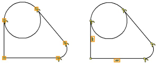
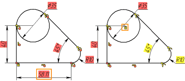
The constraints set the interrelations of the sketch lines and the characteristic position of the lines. Specific dimensions of the drawing will be set using driving dimensions. Activate the ![]() mode in the Ribbon and call the command for dimensions creation <D>. Set the dimension of the diameter of the circle and the radius of rounding: the number of degrees of freedom has become 4. The background color of dimension value is yellow, which, like the presence of degrees of freedom, indicates that the drawing has not yet been fully defined.
mode in the Ribbon and call the command for dimensions creation <D>. Set the dimension of the diameter of the circle and the radius of rounding: the number of degrees of freedom has become 4. The background color of dimension value is yellow, which, like the presence of degrees of freedom, indicates that the drawing has not yet been fully defined.
Next, we put the linear driving dimension, which sets the position of the circle, and the angular, which sets the slope of the segment. The number of degrees of freedom has decreased to 2, and the background of dimensions values is still yellow.
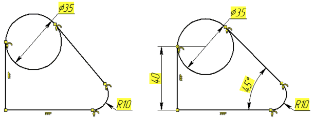
Use the option Show Under Defined lines: all drawing lines are highlighted. This means, that for all the lines of the drawing 2 degrees of freedom are available - moving vertically and horizontally. The sketch itself is already defined by constraints and dimensions, so that it cannot change its geometry, but relative to the origin of coordinates, its position is not specified. The position of the sketch can be defined either by specifying two linear dimensions from the origin of coordinates, or by fixing any point. Fix a point using the Fix constraint.
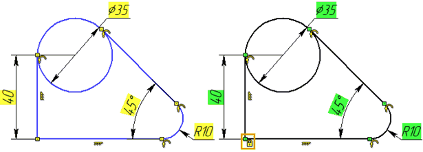
After creating a fixation constraint, the background under the driving dimensions became green, and the number of degrees of freedom became zero. This means that the drawing is fully defined.
If we fix one more point (in general, if we create one more constraint) or put another driving dimension, then the drawing will be over defined. The background under the dimensions will turn red and messages will appear, stating that the constraints are recalculated with errors, since they will begin to duplicate and conflict each other.
