Constraints > Coincident |
  
|
Command call:
Icon |
Ribbon |
|---|---|
|
Draw > Constraints > Constraint > Coincident Workplane > Constraints > Constraint > Coincident |
Keyboard |
Textual Menu |
<SC>><C> |
|
Parameters window of the |
|
<C> |
Coincident |
This constraint creates a connection between two points (one of the points can be the LCS origin) or between a point and a line.
The point of one object will coincide with the point or line of another object. If points (or point and line) do not coincide, when constructing a sketch, then, when using the Coincident constraint, lines will automatically move to such a position, that the points (or point and line) coincide. If a point is bound by Coincidence with another point or line, then any editing or parametrization will keep the coincidence.
If positions of selected points and their parent objects are not fixated by other constraints, then the object to be moved upon applying a coincidence depends on type of objects.
When creating a coincidence between points belonging to objects of any type, except splines, the object, whose point was selected second, gets moved.
When creating a coincidence between a point belonging to a spline and a point belonging to an object of any other type, the non-spline object gets moved, regardless of the order of selection.
When creating a coincidence between points belonging to two splines, the point to be moved is selected arbitrarily by the system.
If position of second object is fixated, then first object gets moved. If both objects are fixated, then the new constraint will throw an error.
If the object to be moved doesn't have fixated points, then it keeps its initial geometry upon moving. Otherwise, instead of moving the whole object, only the selected point gets moved, which results in changes in object's geometry. This rule doesn't apply to splines - their selected points are always moved individually without moving other points.
The constraint allows to select multiple second objects.
Icon of constraint overlaps constrained points.
Examples
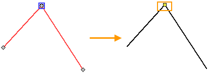
The coincidence of the ends of the straight line segments
Select ![]() the ending point of the segment, then select
the ending point of the segment, then select ![]() the starting point of another segment, and end the input with
the starting point of another segment, and end the input with ![]() or <Ctrl>+<Enter>. The order of points is not important in this case, because they already coincide. The parameters window will indicate the selected objects.
or <Ctrl>+<Enter>. The order of points is not important in this case, because they already coincide. The parameters window will indicate the selected objects.

A yellow square marker in the drawing indicates the coincidence. If the coincidence is set incorrectly, the marker will be red.
In this example specified points coincided before creating the constraint. The difference is, that now, if we move any of the segments, the other segment will be rearranged, so that the points coincide. Before creating the constraint, the segments were independent of each other.

The coincidence of the starting point of the straight segment and the center of the ellipse
Select ![]() the center of the ellipse, then select
the center of the ellipse, then select ![]() the starting point of the segment, and finish the input with
the starting point of the segment, and finish the input with ![]() or <Ctrl>+ <Enter>. If the selected points did not match, then the object selected second will move, so that the points match.
or <Ctrl>+ <Enter>. If the selected points did not match, then the object selected second will move, so that the points match.

The coincidence of the starting point of the straight segment and the circle

Select ![]() the starting point of the segment, then select
the starting point of the segment, then select ![]() the circle, and end the input with
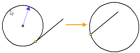
the circle, and end the input with ![]() or <Ctrl>+<Enter>. The circle has moved, so that the starting point of the segment began to coincide with it.
or <Ctrl>+<Enter>. The circle has moved, so that the starting point of the segment began to coincide with it.

You can change the position of the circle and its radius - the starting point of the segment will always coincide with the circle.
Coincidence of Multiple Points

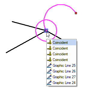
First, select the point, which other points should coincide with, then sequentially select other points with ![]() (in any order) and end input with
(in any order) and end input with ![]() or <Ctrl>+<Enter>. The parameters window will indicate, that multiple second objects have been selected (in this case, four).
or <Ctrl>+<Enter>. The parameters window will indicate, that multiple second objects have been selected (in this case, four).
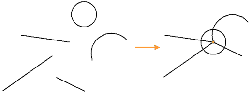
As a result, four constraints will be created for five points - for each pair of the second object with the first one. In the drawing icons of constraints will fully overlap each other. Moving any of the five lines will rebuild the rest.
