Constraints > Fix and Full Fixation |
  
|
Calling the Fix command:
Icon |
Ribbon |
|---|---|
|
Draw > Constraints > Constraint > Fix Workplane > Constraints > Constraint > Fix |
Keyboard |
Textual Menu |
<SC>><F> |
|
Parameters window of the |
|
<F> |
Fix |
The Fix constraint fixes the selected element. You can fix a line or a point. Fixing a point preserves its position. Fixing a line preserves its angle and curvature. Preserved parameters won't change, when creating other constraints or editing a parametric sketch. Fixing a line prevents direct changes of its length and of its points' positions, but doesn't prevent such changes resulting form applying other constraints and driving dimensions. If you want to fully preserve line's length and its points' positions, fix the key points directly in addition to fixing the whole line.
The Fix constraint allows to select multiple objects to be fixed.
Icon of constraint is displayed near midpoint of constrained object.
The ![]() Full fixation command is available in the contextual menu of 2D elements. It applies Fix constraints not only to the selected line, but also to all its key points, thus fully preserving its geometry. Resulting constraints are independent of each other. The Full fixation command may also be applied to a single point: in such case it yields the same result, as the Fix command.
Full fixation command is available in the contextual menu of 2D elements. It applies Fix constraints not only to the selected line, but also to all its key points, thus fully preserving its geometry. Resulting constraints are independent of each other. The Full fixation command may also be applied to a single point: in such case it yields the same result, as the Fix command.
Example
Full fixation as a quick way to fully define a sketch
When creating parametric models, it is important to fully define the sketch. Otherwise, when the control parameters are changed, the under defined lines will be rebuild randomly. Full fixation makes it possible to fix those parts of the sketch that should remain unchanged in the parametric model.
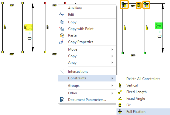
Suppose we have a rectangle whose height is specified by the parameter “a”, while the length of the rectangle and the position of its upper side in the drawing must remain unchanged. We can call the contextual menu for the line of the upper side of the rectangle with the help of ![]() and select the constraint Full fixation. Considering other constraints (which can be created automatically when constructing a rectangle) and the driving dimension, the sketch will be completely defined. This is shown by a green background under the driving dimension and color of the Coincident constraint points.
and select the constraint Full fixation. Considering other constraints (which can be created automatically when constructing a rectangle) and the driving dimension, the sketch will be completely defined. This is shown by a green background under the driving dimension and color of the Coincident constraint points.

Fixing Lines When Creating a Coincidence Constraints
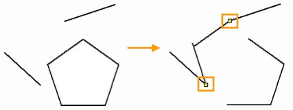
If you create a Coincident constraint between the extreme points of the separate line segments and sides of the polygon, then sides of the polygon may be moved, upon further editing of separate segments.
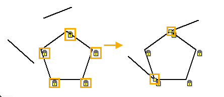
In order to avoid moving of polygon's sides, lets fixate them.

In the ribbon, select the Fix constraint. Using ![]() , we consecutively select all angular points of the polygon, then finish input using
, we consecutively select all angular points of the polygon, then finish input using ![]() or <Ctrl>+<Enter>. Five constraints will be created, which can be seen by the icons that appear in the drawing or in the Model Elements window. Then you can proceed to creation of Coincident constraints. Now further movement of separate segments doesn't affect the sides of the polygon.
or <Ctrl>+<Enter>. Five constraints will be created, which can be seen by the icons that appear in the drawing or in the Model Elements window. Then you can proceed to creation of Coincident constraints. Now further movement of separate segments doesn't affect the sides of the polygon.
