Constraints > Horizontal and Vertical |
  
|
Icon |
Ribbon |
|---|---|
|
Draw > Constraints > Constraint > Horizontal Workplane > Constraints > Constraint > Horizontal |
Keyboard |
Textual Menu |
<SC>><H> |
|
Parameters window of the |
|
<H> |
Horizontal |
Icon |
Ribbon |
|---|---|
|
Draw > Constraints > Constraint > Vertical Workplane > Constraints > Constraint > Vertical |
Keyboard |
Textual Menu |
<SC>><V> |
|
Parameters window of the |
|
<V> |
Vertical |
These two constraint can be applied to straight line segments or axes of an ellipse.
If you apply the Horizontal constraint, then the segment or axis will take the horizontal position and will keep it, when you edit a sketch. Horizontality implies parallelism to X axis .
If you apply the Vertical constraint, then the segment or axis will take the vertical position and will keep it, when editing the sketch. Verticality implies parallel to Y axis.
When applying these constraints to an ellipse, they are applied to its major axis. If you edit the ellipse later, so that the axis, which was major at the moment of constraint's creation, becomes the minor one, then the constraint will be automatically reapplied to another axis.
When applying these constraints, segments and ellipses change their orientation but keep their shape and dimensions.
These constraints allow selection of multiple objects at once.
Icon of constraint is displayed near midpoint of constrained object.
Example
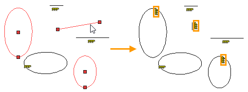
Horizontality and Verticality of Line Segments and Axis of the Ellipse
Let us be given three segments and three ellipses. We create Horizontal constraint for two segments and an ellipse, and Vertical constraint for one segment and two ellipses.
Select the Horizontality constraint in the Ribbon. With the help of ![]() choose two segments and an ellipse. Upon selection, the segments and the major axis of the ellipse become horizontal. We finish input of constraint objects using
choose two segments and an ellipse. Upon selection, the segments and the major axis of the ellipse become horizontal. We finish input of constraint objects using ![]() or <Ctrl>+<Enter>. Three constraints will be created, which can be seen in the drawing by the appeared icons or in the Model Elements window.
or <Ctrl>+<Enter>. Three constraints will be created, which can be seen in the drawing by the appeared icons or in the Model Elements window.

Select the Vertical constraint in the Ribbon. With the help of ![]() choose two ellipses and a segment. Upon selection, the segment and the major axes of the ellipses become vertical. We finish input of constraint objects using
choose two ellipses and a segment. Upon selection, the segment and the major axes of the ellipses become vertical. We finish input of constraint objects using ![]() or <Ctrl>+<Enter>. Three constraints will be created, which can be seen in the drawing by the corresponding icons or in the Model Elements window.
or <Ctrl>+<Enter>. Three constraints will be created, which can be seen in the drawing by the corresponding icons or in the Model Elements window.

When editing lines, which the constraints are applied to, the segments can change length, ellipses can change dimensions of axes, all elements can change position in the drawing, but the angle of the elements will remain the same: segments and major axes of ellipses will remain horizontal and vertical.