Constraints > Horizontal and Vertical Alignment |
  
|
Icon |
Ribbon |
|---|---|
|
Draw > Constraints > Constraint > Horizontal Alignment Workplane > Constraints > Constraint > Horizontal Alignment |
Keyboard |
Textual Menu |
<SC>><D> |
|
Parameters window of the |
|
<D> |
Horizontal Alignment |
Icon |
Ribbon |
|---|---|
|
Draw > Constraints > Constraint > Vertical Alignment Workplane > Constraints > Constraint > Vertical Alignment |
Keyboard |
Textual Menu |
<SC>><G> |
|
Parameters window of the |
|
<G> |
Vertical Alignment |
Constraints allow you to align two points of two different lines horizontally or vertically. If you apply the Horizontal alignment constraint, then two points will have the same coordinate along the Y axis. If you apply the Vertical alignment constraint, then two points will have the same coordinate along the X axis.
If positions of selected points and their parent objects are not fixated by other constraints, then the object to be moved upon applying a coincidence depends on type of objects.
When creating an alignment between points belonging to objects of any type, except splines, the object, whose point was selected second, gets moved. Same rule applies to alignment between points belonging to two splines.
When creating an alignment between a point belonging to a spline and a point belonging to an object of any other type, the non-spline object gets moved, regardless of the order of selection.
If position of second object is fixated, then first object gets moved. If both objects are fixated, then the new constraint will throw an error.
If the object to be moved doesn't have fixated points, then it keeps its initial geometry upon moving. Otherwise, instead of moving the whole object, only the selected point gets moved, which results in changes in object's geometry. This rule doesn't apply to splines - their selected points are always moved individually without moving other points.
These constraints allow to select multiple second objects.
Icons of constraint are displayed near of each constrained points. If there are multiple constraints of this type applied to the same point, then all of these constraints are represented by a single icon. When pointing the cursor to an icon representing multiple constraints, you can select a particular constraint using selection hints.
By default, a numerical index is displayed near constraint's icon in drawing. It is the number of the group of constraints. If any of a constraint's objects belongs to the same line, as any of another constraint's objects, such constraints are put into the same group. Indexes display may be disabled in system options.
Example
Horizontal and Vertical Alignment of Arc's and Spline's End Points
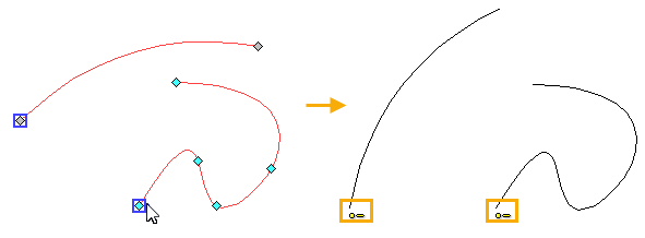
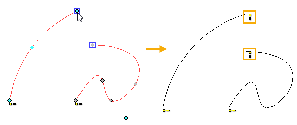
Let us be given an arc and spline. Let us make it so, that the starting points of the lines will be aligned horizontally, and the ending will be aligned vertically.
We select the Horizontal alignment in the Ribbon, then with the help of ![]() we select the starting point of the arc and the starting point of the spline. The arc is moved in such a way so that its starting point is on the same horizontal line with the starting point of the spline. Finishing objects input. In the drawing, the icons of the constraint appear next to the selected points. The points can be at any distance from each other, but now they will always remain on the same horizontal line.
we select the starting point of the arc and the starting point of the spline. The arc is moved in such a way so that its starting point is on the same horizontal line with the starting point of the spline. Finishing objects input. In the drawing, the icons of the constraint appear next to the selected points. The points can be at any distance from each other, but now they will always remain on the same horizontal line.

Next, select the Vertical alignment in the Ribbon, and then use ![]() to select the end point of the arc and the end point of the spline. The arc is moved in such a way so that its ending point is on the same vertical line with the ending point of the spline. Finish objects input. In the drawing, a constraint icon appeared next to the points. Points can be at any distance from each other, but now always on the same vertical.
to select the end point of the arc and the end point of the spline. The arc is moved in such a way so that its ending point is on the same vertical line with the ending point of the spline. Finish objects input. In the drawing, a constraint icon appeared next to the points. Points can be at any distance from each other, but now always on the same vertical.
