Find and Infer Constraints |
  
|
The command can be called in one of the following ways:
Icon |
Ribbon |
|---|---|
|
Draw > Constraints > Find and Infer Constraints Workplane > Constraints > Find and Infer Constraints |
Keyboard |
Textual Menu |
<IS> |
|
The command allows you to create constraints and driving dimensions for previously created sketch lines. The logic of the automatic creation of constraints and dimensions includes algorithms, that prevent over-defining the drawing during automatic parametrization.
Upon calling the command, select in the drawing window lines to be constrained. Clicking ![]() a line adds it to the selection. You can select multiple objects at once using frame or curve selection. In order to instantly select all graphic lines of the active view, use the following automenu option:
a line adds it to the selection. You can select multiple objects at once using frame or curve selection. In order to instantly select all graphic lines of the active view, use the following automenu option:
|
<*> |
Select All Elements |
Alternatively, you can select lines prior to calling the command.
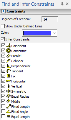
The command's parameters window is split into the Constraints and Dimensions tabs, which contain the parameters of constraints and dimensions creation respectively. The number of drawing's Degrees of Freedom, the checkbox allowing to Show Under Defined Lines and control for selecting the Color of under-defined lines highlighting are located in the upper section of the Constraints tab (see the Graphic Lines' Degrees of Freedom section).
Next, there is the Infer Constraints checkbox. If it's disabled, then constraints won't be created. If it's enabled, then finishing the input (![]() or <Ctrl>+<Enter>) leads to automatic creation of constraints. Types of created constraints are defined by enabling checkboxes in the list of constraints types located in the bottom section of the tab. The constraints are applied using the same logic as the automatic constraints creation within the Sketch commands.
or <Ctrl>+<Enter>) leads to automatic creation of constraints. Types of created constraints are defined by enabling checkboxes in the list of constraints types located in the bottom section of the tab. The constraints are applied using the same logic as the automatic constraints creation within the Sketch commands.
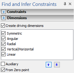
The Create driving dimensions checkbox is located at the top of the Dimensions tab. If it's disabled, then dimensions won't be created. If it's enabled, then finishing the input (![]() or <Ctrl>+<Enter>) leads to automatic creation of driving dimensions. Types of created dimensions are defined by enabling checkboxes in the list of dimension types located below. The priority of creating dimensions of certain types depends on the order of types in the list. Select a type in the list by clicking
or <Ctrl>+<Enter>) leads to automatic creation of driving dimensions. Types of created dimensions are defined by enabling checkboxes in the list of dimension types located below. The priority of creating dimensions of certain types depends on the order of types in the list. Select a type in the list by clicking ![]() it and use the
it and use the ![]() Up and
Up and ![]() Down buttons located below the list, to move the selected type up or down the list. Aside from the buttons there are following checkboxes below the list:
Down buttons located below the list, to move the selected type up or down the list. Aside from the buttons there are following checkboxes below the list:
•Auxiliary
If the checkbox is enabled, all created driving dimensions will be auxiliary, and, therefore, non-printable.
•From Zero point
If the checkbox is enabled, additional driving dimensions are created in order to define a position of lines in relation to the origin of the active view's coordinate system.
Even if the constraints creation is disabled, the driving dimensions won't be created for the geometry, which can be defined by constraints. E.g. an angular dimension between lines normal to each other is never created, as such geometry can be defined by the Perpendicular constraint.
Upon creating driving dimensions via this command, the existing informational dimensions are automatically converted to driving ones.
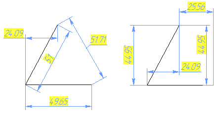
Different results of automatic creation of auxiliary driving dimensions
fro the same set of lines, caused by the different order of dimension types in the list
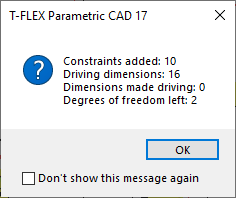
As you selected graphic lines and set the desired parameters of constraints and dimensions creation, finish the input using ![]() or <Ctrl>+<Enter>. In result, constraints and dimensions will be created for selected lines in accordance with the specified parameters. The results of the command application, such as number of created elements and number of remaining drawing's degrees of freedom are provided the informational window.
or <Ctrl>+<Enter>. In result, constraints and dimensions will be created for selected lines in accordance with the specified parameters. The results of the command application, such as number of created elements and number of remaining drawing's degrees of freedom are provided the informational window.
Example
Automatic Parametrization of Sketch After Construction
Let's explore the example from the Driving Dimensions and Infer Constraints sections. Suppose the sketch has already been constructed, but so far there are no constraints on it. Call the Find and Infer Constraints command. In the command parameters window, we can see that the current number of degrees of freedom of the sketch is 20. In order to demonstrate the command's operational algorithm, let's start with disabling the creation of driving dimensions and leave only the creation of constraints enabled. Next, use the select all the lines option in the automenu, and use the ![]() or <Ctrl>+<Enter> to finish the input.
or <Ctrl>+<Enter> to finish the input.
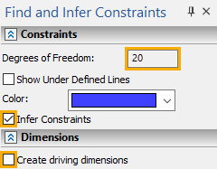
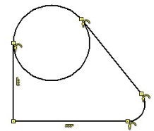
11 constraints were created automatically - information on automatically created constraints and dimensions is displayed in a special message after the completion of Find and Infer Constraints command. Auto-created constraints set the connection of all graphic lines. 5 coincidences were created: 2 coincidence of the circle and the extreme points of the segments, 2 coincidence of the extreme points of the arc and the extreme points of the segments and 1 coincidence of the extreme points of the segments between each other. Thus, all successive lines are parametric interconnected. 4 tangencies were created: 2 tangencies between the circle and segments and 2 tangencies between an arc and segments. One Verticality constraint was created for vertical segment and one Horizontality constraint for horizontal segment.
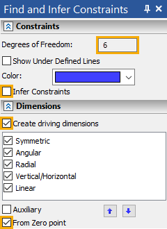
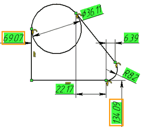
Again, go to the command Find and Infer Constraints. In the parameters window of the command, you can see that, after creating constraints, the degrees of freedom of the drawing were reduced to 6. Let's create driving dimensions. Since we have already created the constraints, then we will disable the checkbox for creating constraints, and we will enable the checkbox for creating driving dimensions. Additionally enable the checkbox for creating dimensions from zero, i.e. from the origin - this will allow us to completely define the drawing. Again, select all the lines, and use the ![]() or <Ctrl>+<Enter> to finish the input. The message window displays information about the created dimensions and constraints. Close the window. The driving dimensions were automatically created, which established a clear interrelation of all lines of the drawing, taking into account the constraints, and the specified driving dimensions from the origin were also created. The automatically created driving dimensions completely defined the drawing, which is indicated by to the green background of the dimension values. It should be noted, that it is not necessary to create constraints and driving dimensions separately — it is more convenient and faster to do this at the same time.
or <Ctrl>+<Enter> to finish the input. The message window displays information about the created dimensions and constraints. Close the window. The driving dimensions were automatically created, which established a clear interrelation of all lines of the drawing, taking into account the constraints, and the specified driving dimensions from the origin were also created. The automatically created driving dimensions completely defined the drawing, which is indicated by to the green background of the dimension values. It should be noted, that it is not necessary to create constraints and driving dimensions separately — it is more convenient and faster to do this at the same time.