Line. 2D Constructs |
  
|
The command can be called in one of the following ways:
Icon |
Ribbon |
|---|---|
|
Draw > Construct > Line > Line Assembly > Assembly > Line > Line Workplane > Construct > Line > Line |
Keyboard |
Textual Menu |
<L> |
Construct > Line |
The command creates infinite straight construction lines. Same as other construction elements, these lines are displayed in a non-printable thin dashed line.
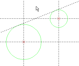
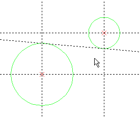
Depending on the applied methods of creation, lines may either be independent, or defined via geometric relations with other construction elements. Examples of such relations include passing through a node; parallelism, symmetry, distance or angle in relation to other straight line; tangency to a curve; splitting a distance between two nodes in defined ratio. Defining geometric relations require selecting parent elements. For instance, defining a tangency requires selection of a tangent curve. When selecting such curve, the applied tangency configuration depends on the position of the cursor.


Independent lines may be created using the following methods:
•perpendicular lines using coordinates;
•perpendicular lines through LCS origin;
•horizontal line using ordinate;
•vertical line using abscissa.
Such lines may be used as base objects for creating all other drawing elements. Additionally, coordinates of such lines may be defined via variables, in order to create a parametric drawing. In such case, the variables will be parents of the lines. Moreover, variables may be used for defining geometric relations expressed via numeric parameters (angle, distance, proportionality factor).
The command has four main modes:
•Creating a pair of perpendicular lines (horizontal and vertical) with a node at intersection/
This mode is activated using the following automenu option:
|
<X> |
Create two crossing Lines and Node |
•Creating a horizontal line.
This mode is activated using the following automenu option:
|
<H> |
Create horizontal Line |
•Creating a vertical line.
This mode is activated using the following automenu option:
|
<V> |
Create vertical Line |
•Creating a line passing at an arbitrary angle.
This mode is active by default after calling the command, which is indicated by the automatic activation of the line selection option:
|
<L> |
Select related Line |
Moreover, there are special modes, which can be activated via the following automenu options:
|
<T> |
|
|
<U> |
|
|
<A> |
|
|
<W> |
Following options are available in the automenu, upon calling the command, in addition to the ones listed above:
|
<P> |
Set Line Parameters |
Invokes the line parameters dialog.
|
<N> |
Select Node |
|
<C> |
Select tangent Circle |
|
<E> |
Select ellipse to create Line |
|
<S> |
Select spline |
These option can be used in various line creation methods for selecting 2D nodes for the line to pass through, or curves for the line to be tangent to.
|
<F4> |
Invokes the 2D construction elements editing command.
|
<Esc> |
Exit command |
When working with the command, the set of available options may vary depending on the applied method of line creation and stage of its execution.
In the meantime, you can cancel the selection and return to the initial state of the command at any moment, using the following automenu option:
|
<Esc> |
Cancel selection |
Creating 2D nodes
At any stage of working with the command, pressing <Space> creates a connected 2D node at the nearest (to the cursor) intersection of construction lines. If a 2D node already exists at the nearest intersection, or if there are no intersections on the current page, then pressing <Space> has no effect.
Creating construction lines based on graphic lines
When creating lines based on other lines (tangent, parallel, symmetric), only construction lines can be used. However, you may also select a graphic line (straight, circle, circular arc, ellipse, elliptic arc) by moving the cursor over it and pressing ![]() or <Enter>. Upon selecting a graphic line, a construction line (straight, circle or ellipse) coinciding with the selected graphic line gets created automatically. Then, the resulting construction line is used as parent object of the current line.
or <Enter>. Upon selecting a graphic line, a construction line (straight, circle or ellipse) coinciding with the selected graphic line gets created automatically. Then, the resulting construction line is used as parent object of the current line.
Topics in this section: