Edit 2D Constructs |
  
|
The command can be called in one of the following ways:
Icon |
Ribbon |
|---|---|
|
Draw > Additional > 2D Construction Sheet Metal (2D) > Additional > 2D Construction Workplane > Additional > 2D Construction |
Keyboard |
Textual Menu |
<EC> |
Edit > 2D Construction |
The Edit Construction command is provided for editing construction lines. The command allows editing all kinds of 2D construction elements except 2D nodes. Selecting a 2D node within this command automatically launches the dedicated nodes editing command.
The transparent editing of 2D elements is enabled by default (Options > 2D > 2D > Transparent element editing), so the editing command is launched automatically upon selecting a construction element in a drawing window.
Elements selection
If none of the elements were selected, then upon calling the command you have to select in the drawing window elements to be edited.
A click ![]() within said window selects a construction line nearest to the point of clicking.
within said window selects a construction line nearest to the point of clicking.
Pressing <Enter> selects a construction line nearest to the current position of the cursor.
Pressing <Space> creates a connected 2D node at the intersection of construction lines nearest to the current position of the cursor.
Use automenu options to select lines of a particular type.
Use automenu options or selector frame to select multiple lines.
Upon selecting a line, its editing begins and the set of automenu options changes. Select element and its direct parents get highlighted.
Editing elements' parameters
If a position of a straight line, diameter of a circle, second diameter of an ellipse are not defined by other elements, then such parameters start dynamically changing in accordance with cursor position during element's editing. Just set the desired configuration by moving the cursor and click ![]() or press <Enter> to confirm changes.
or press <Enter> to confirm changes.
To specify the exact value of the placement parameter, use the parameters window ![]() or the parameters dialog
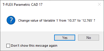
or the parameters dialog ![]() . If the entity was driven by a variable, the system will output a warning.
. If the entity was driven by a variable, the system will output a warning.

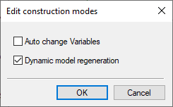
To avoid the system warnings, call the parameters dialog ![]() before selecting any entities. A dialog box will come up, where you should enable the Auto change Variables checkbox. Here you can also enable or disable the Dynamic model regeneration.
before selecting any entities. A dialog box will come up, where you should enable the Auto change Variables checkbox. Here you can also enable or disable the Dynamic model regeneration.

If you have selected several elements for editing, then, upon calling the parameters dialog, you need to set the parameters of multiple editing first, and then proceed to editing the parameters of the constructions.
When modifying the values of construction parameters it is possible to use Relations that appear on element selection. These Relations are temporary. They will automatically disappear on editing finish. To modify the values of construction parameters with the help of relations it is necessary to turn off the dynamic regeneration mode (option ![]() ).
).

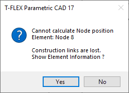
It is possible that some construction entity can't be recreated after modifying parameter values due to geometrical incompatibilities among the entities. In such a case, the system will output an error message and specify the particular failing relation.

Automenu options
Following options are available upon calling the command without selecting an element:
|
<P> |
Set command options |
Invokes the Edit construction modes dialog.
|
<V> |
Dynamic model regeneration mode |
If this option is active, then, along with the dynamic preview of selected element's changes, the preview resulting child elements changes is also displayed.
If this option is inactive, then, along with the dynamic preview of selected element's changes, the initial configuration is also displayed.
Alternatively the dynamic model regeneration mode may be enabled/disabled in the Edit construction modes dialog.
|
<L> |
Select Line |
|
<C> |
Select Circle |
|
<E> |
Select Ellipse |
|
<S> |
Select Spline |
|
<N> |
Select Node |
These options can be used to select elements for editing.
Upon activating an option via the keyboard, an element of the corresponding type nearest to the cursor get selected automatically.
Upon activating an option via the mouse, you have to click ![]() within the drawing window, which results in automatic selection of an element of the corresponding type nearest to the clicking position.
within the drawing window, which results in automatic selection of an element of the corresponding type nearest to the clicking position.
Alternatively you can select construction elements without activating these options: just move the cursor over an element and click ![]() .
.
The spline selection option may also be used for selecting a 2D path, offset curve or function spline.
|
<Q> |
Update All Line Extents |
Applies the Trim command to all construction straight lines and circles at all pages of the current document.
|
<*> |
Select All Elements |
Selects all construction lines at all pages of the current document.
|
<R> |
Select element from list |
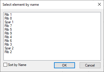
Invokes the dialog containing the list of all available named construction lines. Named are the lines, whose names are defined manually by the user. The content of the list doesn't depend on the active page - all named lines of the current document are displayed. By default, lines are sorted by IDs. Enable the checkbox at the bottom of the dialog if you want to Sort them by Name. Select ![]() a desired line in the list and press ОК. For multiple selection use
a desired line in the list and press ОК. For multiple selection use ![]() +<Shift> (select all elements from the one under the cursor to the one currently selected inclusively) and
+<Shift> (select all elements from the one under the cursor to the one currently selected inclusively) and ![]() +<Ctrl> (includes/excludes an element under the cursor into/from the selection).
+<Ctrl> (includes/excludes an element under the cursor into/from the selection).

|
<Esc> |
Exit command |
Upon selecting multiple elements for editing, the set of available automenu option changes to following:
|
<P> |
Set selected element(s) parameters |
Invokes parameters dialog for all selected lines at once (See the Multiple 2D Elements Editing section).
|
<K> |
Break link with variable |
Replaces variable by constants in parameters of selected elements.
|
<I> |
|
|
<Del> |
Delete selected Element(s) |
|
<Esc> |
Cancel Selection |
Upon selecting a single element for editing, following options are always available:
|
<P> |
Set Construction Line Parameters |
|
<V> |
Dynamic model regeneration mode |
|
<O> |
Create Name for Selected Element |
|
<I> |
|
|
<Del> |
Delete selected Element(s) |
|
<Esc> |
Cancel Selection |
Upon selecting straight lines, circles, ellipses and offset curves, the following option is additionally available:
|
<K> |
Break link with variable |
Replaces variable by constants in parameters of the selected element.
Upon selecting straight lines and circles, following options are additionally available:
|
<T> |
Update selected Line(s) extents |
Applies the Trim command to the selected lines.
|
<M> |
Modify Construction Line relations |
Activating this option launches the command of creating a line of the selected type, so you can re-create it from the scratch. Unlike initial creation of the line, during re-creation the pre-editing configuration of the line remains on the screen, as well as its parents. During re-creation you shouldn't select the initial configuration of the line or its child element as the support geometry. Otherwise, the system will throw a recursion error and changes will be canceled.
Moreover, there are additional automenu options for editing elements of particular types. Such options, as well as other specifics of editing lines of some types are described in the Edit Circles, Edit 2D Paths and Edit Splines sections.
Topics in this section: