Edit 2D Node |
  
|
Icon |
Ribbon |
|---|---|
|
|
Keyboard |
Textual Menu |
<EN> |
Edit > Construction > Node |
Moreover, the nodes editing command is launched automatically from the Edit construction command upon selecting a node.
The transparent editing of 2D elements is enabled by default (Options > 2D > 2D > Transparent element editing), so the editing command is launched automatically upon selecting a node in a drawing window.
Following automenu options are available, upon launching the command without pre-selected node:
|
<*> |
Select All Elements |
|
<R> |
Select element from list |
|
<Esc> |
Exit command |
Next you have to select a node for editing. Clicking ![]() in the drawing window or pressing <Enter> selects a node nearest to the current cursor position.
in the drawing window or pressing <Enter> selects a node nearest to the current cursor position.
You can select several nodes at once using frame or curve selection.
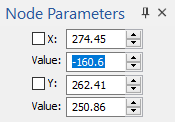
Upon selecting nodes, their editing begins. Free and semi-connected nodes start following the cursor. If a single node is selected, then the parameters window contains input boxes of parameters defining this node's position (X and Y coordinates, dX and dY offsets, coefficient, distance). The set of available parameters depends on the method of node's creation. Unlike the creation mode, two input boxes are displayed fro each parameter during editing:
•Main input box, whose name corresponds to the parameter's name, contains the non-edited value of the parameter.
•The Value input box contains the value of the parameters corresponding to the current cursor's position.
Checkboxes located to the left of the main input boxes work in the same way as during node's creation, but fixing values in the Value box instead of the main one.

Pressing <Enter> or clicking ![]() in the drawing window fixates new positions of nodes and finishes editing.
in the drawing window fixates new positions of nodes and finishes editing.
Upon selecting several nodes following automenu options are available:
|
<P> |
Set selected element(s) parameters |
Invokes the parameters dialog for selected elements at once (See the Multiple 2D Elements Editing section).
|
<J> |
Join free Nodes |
Replaces all selected nodes by a single one, which leads to changes in child elements. If there is a single connected node among the selection of free nodes, then all free nodes are replaced by the connected one. If all selected elements are free, then they are replaced by the node, that was selected last. If there are several connected nodes in the selection, then this option has no effect.

|
<O> |
Create Name for selected Element |
Invokes the dialog, where you can type in the Starting Name. Upon pressing OK all selected nodes will be renamed. New names will contain of the Starting Name and ordered number of a node within the selection.

If a single node is selected, them the exact Element Name can be typed in instead of the Starting Name.

|
<N> |
Select existing Node |
Allows adding nodes to the selection.
|
<I> |
|
|
<Del> |
Delete selected Element(s) |
|
<Esc> |
Cancel selection |
Upon selecting a single node following automenu options are available:
|
<P> |
Set selected element(s) parameters |
|
<V> |
Dynamic model regeneration mode |
If this option is active, as a node follows the cursor, its child elements changes preview is displayed.
|
<O> |
Create Name for selected Element |
|
<B> |
Break Node |
Replaces a single node, which has several child elements, by multiple nodes. In result, an individual parent node is created for each child element, so its position can be changed independently of other elements. This option only affects free nodes.
|
<F> |
Convert to Free Node |
This option is available only for non-free nodes not related to construction lines. It breaks the link between the node and its parent elements and converts the node into free one.
|
<N> |
Select existing Node |
|
<I> |
|
|
<Del> |
Delete selected Element(s) |
|
<Esc> |
Cancel selection |
See Also: