Edit 2D Paths. 2D Constructs |
  
|
If a 2D path is selected in the construction lines editing command, then pressing <Enter> or clicking ![]() anywhere within the drawing window enables the path's contour editing mode.
anywhere within the drawing window enables the path's contour editing mode.
Path's contour editing allows you to add or remove anchor points; choose another construction line connecting the nodal points of a separate section of the path; change the direction of the path, change the numbering of points, as well as set new parameters.
Modifying relations between construction lines
To modify the type of a particular path segment, do the following steps:
•Select a path ![]() ;
;
•Using the mouse ![]() , select the path segment whose type needs to be modified;
, select the path segment whose type needs to be modified;
•Select ![]() a construction entity defining the new type of the path segment: line, circle, ellipse and spline (including other 2D paths). Selection of a construction entity is done using the appropriate option. The end nodes of the path segment being edited must belong to the selected construction entities;
a construction entity defining the new type of the path segment: line, circle, ellipse and spline (including other 2D paths). Selection of a construction entity is done using the appropriate option. The end nodes of the path segment being edited must belong to the selected construction entities;
• Exit the particular path segment editing mode by right-clicking ![]() or pressing <Esc> on the keyboard;
or pressing <Esc> on the keyboard;
• Confirm changes by the option ![]() or <Ctrl>+<Enter>.
or <Ctrl>+<Enter>.

Creating additional nodal points on the path contour
To create additional nodal points of the path contour, you must perform the following set of actions:
•choose a path ![]() ;
;
•select a site for editing ![]() ;
;
•select the option Add point mode;
|
<I> |
Add new points |
•select the position of the new point ![]() ;
;
•exit edit mode ![]() ;
;
•accept changes ![]() or <Ctrl + Enter>.
or <Ctrl + Enter>.

Deleting a node inside path contour
To remove the nodal point of the path, you must perform the following set of actions:
•choose a path ![]() ;
;
•select a section of the path ![]() that is limited by the node that you want to delete;
that is limited by the node that you want to delete;
•select a node ![]() ;
;
•press the <Del>;
•accept changes ![]() or <Ctrl + Enter>.
or <Ctrl + Enter>.

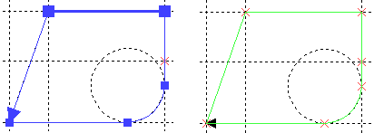
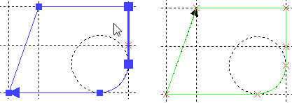
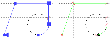
Consider an example in which a straight section of the path must be replaced by a section along an arc of a circle. In this case, the points of tangency of the circle do not coincide with the points of start and end of the rectilinear section.
•choose a path ![]() ;
;
•select the section of the path ![]() that you want to change;
that you want to change;
•select and move the first node of the site to the point of tangency of the line and the circle (moving the node is described in the subsection above);
•select and move the second site node to the point of tangency of the line and the circle;
•select the section of the path ![]() that you want to change again;
that you want to change again;
•select the type of line according to which the path should follow (in this case, a circle);
|
<C> |
Select circle |
|
<E> |
Select ellipse |
|
<S> |
Select spline |
•indicate the line ![]() (in this case, the circle) in the drawing;
(in this case, the circle) in the drawing;
•accept changes ![]() or <Ctrl + Enter>.
or <Ctrl + Enter>.

Displaying the contour point numbers
To toggle the display of the contour point numbers of a 2D path, use the option:
|
<Q> |
Show/Hide contour point numbers |
With the option turned on, the points in the path are enumerated based on their position in the path and the path direction. A point number is displayed next to the respective node. When several subsequent points of a contour coincide, their numbers are displayed next to each other, separated by commas.

Delete contour
To delete a contour, use the option:
|
<Del> |
Delete selected contour |
Edit closed paths
For closed paths, three additional options are available:
|
<R> |
Change the direction of the path to the opposite |

|
<F> |
Move start point forward |

|
<B> |
Move start point back |
