Parameters Dialog of Line. 2D Constructs |
  
|
The parameters dialog ![]() of a straight construction line can be invoked in one of the following ways:
of a straight construction line can be invoked in one of the following ways:
•by double-clicking ![]()
![]() the line in drawing window or in
the line in drawing window or in ![]() Model Elements window;
Model Elements window;
•from the contextual menu, invoked by clicking ![]() the line in drawing window or in
the line in drawing window or in ![]() Model Elements window;
Model Elements window;
•from the dynamic toolbar, displayed upon selecting the line in drawing window, if the transparent editing of 2D elements is disabled;
•from the automenu of the ![]() Line command;
Line command;
•from the automenu of the ![]() 2D constructs editing command, after selecting a line.
2D constructs editing command, after selecting a line.
The dialog called from the automenu of the ![]() Line command defines parameters of lines created further. The dialog called by other means defines parameters of the selected line.
Line command defines parameters of lines created further. The dialog called by other means defines parameters of the selected line.


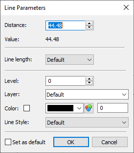
One of the following parameters can be displayed at the top of the dialog for existing lines, if such parameter was used for defining the line:
•Distance
This parameter is available for lines constructed parallel to other lines using distance. This is the distance between the current line and the line selected as the reference for the construction.
•Angle
This parameter is available for lines created at an angle to horizontal, or at an angle to other line.
•Factor
This parameter is available for proportional lines. This is the proportionality coefficient of distances between the created line and selected 2D nodes.
•X or Y Coordinate
This parameter is available for horizontal and vertical lines, including ones constructed in the perpendicular lines creation mode, if position was defined by specifying coordinates. This is the distance between the line and origin of LCS of the view the line belongs to.
Value. Displays numerical value of the Distance, Angle, Factor or Coordinate. May be useful, when the parameter is defined via a variable or expression.
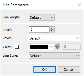
Line length. See the Trim and Restore Construction Lines section.
Level. Places the line on the particular visibility level. Levels help hiding certain elements from display.
Layer. Allows placing the line on a certain layer.
Color. Upon enabling the checkbox, you can select the color to be used for displaying the current element. If the checkbox is disabled, the element is displayed in default color. Default color is defined in system options (Options > Colors > Common > Default Construction Color). Moreover, document parameters allow you to define a separate color of construction lines belonging to a particular page (Document Parameters > Page > Colors > Colors > Construction Line Color).
Line Style. In the drop-down lists you can choose one of the following options for displaying the line:
•Default
•Solid
•Dash
•Long Dash
•Dash Dot
Set as default. Enabling this checkbox means, the current parameter settings in this dialog (with the exception of the Distance, Angle and Coordinate parameters) will be used from now on for all new construction lines of any type.