2D Connector |
  
|
Calling the command:
Icon |
Ribbon |
|---|---|
|
Draw > Insert > Connector Assembly > Assembly > Connector Workplane > Insert > Connector |
Keyboard |
Textual Menu |
|
|
The connector is used to automate the binding of fragments in an assembly drawing.
Upon calling the command, you can anytime switch between creation of fixing vectors, 2D coordinate systems and 2D connectors using the following automenu options:
|
<F> |
|
|
<L> |
|
|
<C> |
Create Connector |
Following options are also available:
|
<Ctrl>+<Enter> |
Create fixing vector by one point (Finish Input) |
|
<A> |
Set Snap Elements |
|
<N> |
Select Node |
|
<F4> |
(Edit fixing vector, 2D LCS or 2D connector) |
|
<Esc> |
Exit command |
General information
A connector is a construction element used for snapping 2D fragments to it. In addition to the geometric position (the position of the origin of the coordinate system and the direction of the axes) the connector can also store a set of variables with certain values. If a connector is selected when applying a fragment to an assembly, that the selected fragment's fixing vector is combined with the connector vector of the assembly. In addition, the values of the connector variables are automatically assigned to the eponymous external variables of the fragment. If there are no variables with the matching names in the connector, then the external variables of the fragment will have the value specified in the fragment document.
In order to create a connector, upon calling the command, specify the desired set associated elements and insertion rules, and then specify one or two point defining the connector.
Setting associated elements for a connector
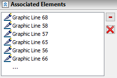
To define the graphic lines associated with the connector, use the option:
|
<A> |
Set snap elements |
After selecting the option, the system enters the mode for selecting drawing lines that will activate the connector when you hover over them. To attach elements to the connector, select them with the mouse in the drawing window. The selected elements are added to the list of associated elements in the parameters window.

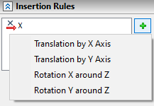
For a connector, so-called "insertion rules" can be additionally defined. These are additional transformations of movement or rotation relative to the coordinate axes of the connector, which the system will automatically prompt the user to perform when the fragment is attached to this connector. For example, when tying a nut to a bolt connector, in practice it is always necessary to specify additional movement of the nut along the bolt axis. Therefore, when designing a bolt model, you need to specify in the insertion rules for its connector to move along the X-axis of the connector.

In order to create a connector, upon calling the command, specify one or two points by moving the cursor over them and pressing ![]() or <Enter>.
or <Enter>.
You can use arbitrary point of a drawing, or select existing 2D nodes, characteristic points of graphic lines and intersections of construction lines using object snappings. Selecting a characteristic point of a graphic line or an intersection of construction lines results in automatic creation of a connected 2D node there. The following automenu option can be used for selecting existing 2D nodes:
|
<N> |
Select Node |
Upon activating this option, pressing ![]() anywhere within drawing window results in selecting a nearest existing 2D node.
anywhere within drawing window results in selecting a nearest existing 2D node.
If you finish the input using the ![]() (<Enter>) option, upon specifying one point, a connector defined by a single point will be created.
(<Enter>) option, upon specifying one point, a connector defined by a single point will be created.
Upon specifying two points, input gets finished automatically.
Upon finishing the input, the connector's parameters dialog will appear. Specify desired parameters and press OK.
After pressing OK, the connector will be displayed in the drawing.
Topics in this section: