2D Fragment's Fixing Elements |
  
|
You can create parametric drawings in the T-FLEX CAD system. Any drawing can be inserted into another drawing. The drawing inserted into another drawing is called a fragment.
In the T-FLEX CAD system, there are two ways of positioning a parametric fragment .
•Usage of Fixing vectors.
In this method, you create a fragment drawing first and define a fixing vector in it. There can be several fixing vectors.
Fixing vector defines the origin and the positive x-axis direction of fragment's local coordinate system in an assembly, thus allowing to change position and orientation of a fragment upon its insertion.
When inserting fragments containing fixing vectors, you may also use connectors created in the assembly.
2D connector is a construction element that is intended for snapping other elements to it. If a connector is selected when inserting a fragment into an assembly, than the fragment's fixing vector gets coincided with the connector's vector. In addition to the geometric position (the position of the origin of the coordinate system and the direction of the axes), the connector can store other (dimensional or non-dimensional) information necessary to "connect" other elements to it. This information is stored as named values, which can be either constants or variables. These values are used to set the values of eponymous external variables of fragments that are connected to them.
•Usage of fixing points.
In this method, fragment's drawing is built according to certain rules. For vertical and horizontal construction lines, reserved external variable names are set as parameters. Then the system defines the intersection point of such lines as the fixing point of the fragment. There can be several fixing points. Upon inserting a fragment into an assembly, you specify coordinates of fixing points, and such coordinates are used as values of corresponding external variables
Usage of fixing vectors, connectors and fixing points allows to obtain various different configurations of the same fragment, upon inserting it into an assembly.
The main difference between the fixing vector and fixing point approaches is in the sequence of creation steps of the fragment drawing. When using fixing vectors, you need to create the drawing first, and then specify the fixing vectors. When using the fixing points, one has to create fixing points first, and then build the drawing of the part based on the fixing points.
There are also differences in the uses of fixing vectors and points. Fragments with fixing vectors are created as follows: first, the image of the fragment is formed, taking into account the visibility layers. Next, the complete image is moved to the specified point and rotated by the specified angle without distortions. Fragments with fixing points are created differently: upon specifying the fixing points, all construction elements dependent on those points are rebuilt first, and then the image of the fragment is obtained.
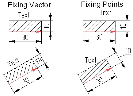
This difference in forming the fragment image on the assembly drawing leads to differences that can be illustrated by the following example. Let's create identical fragments with different fixing provisions. Insert these fragments into a drawing, rotated by the same angle. The fragment that uses a fixing vector, exposes a change in the hatch angle, nonstandard dimension placement (with the automatic dimension text orienting functionality disabled), and a changed angle of a text. The fragment that uses fixing points shows the hatch angle preserved, the dimension "10" rotated per the standard, and the text angle maintained as well.

The mentioned differences shall not be considered shortcomings; rather, those are features that can be exploited in certain design situations.
Topics in this section: