Fixing Point |
  
|
A one or several fixing points can be used for positioning a 2D fragment in an assembly. Fixing point is created as the intersection of vertical and horizontal lines, the positions of which are defined by external variables with reserved names. For vertical lines, variable names range from x1 to x99; for horizontal lines - from y1 to y99. The number at x and y corresponds to the fixing point number and must be the same for the vertical and the horizontal lines that define one fixing point. There can be up to nine fixing points in a drawing.


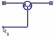
Example of a transistor fragment with three fixing points
Since T-FLEX CAD always threats variables named x1, y1, x2, y2, etc. as coordinates of fixing points, it is recommended to avoid usage of such names for variables serving different purpose.
You should define necessary fixing points before creating a drawing of 2D fragment. All subsequent elements of the drawing must be created relative to the straight lines that define these points. For example, if we want to use a circle as a fragment, which we could then place in various places in other drawings, we must first create horizontal and vertical lines, and then a circle with a center at the point of their intersection.
Defining a fixing point
The following automenu option available in the ![]() perpendicular lines creation mode of the Line command can be used for defining fixing points:
perpendicular lines creation mode of the Line command can be used for defining fixing points:
|
<F> |
Create insertion Point for Fragment (xn,yn) |
Usage of this option is described in the Perpendicular Straight Construction Lines through Fragment's Fixing Point section. In result, two new straight construction lines get created and positions of these lines are defined via variables defining their intersection as fragment's fixing point.
Alternatively, a fixing point may be defined using already existing horizontal and vertical lines. To do so, define positions of these lines via corresponding external variables using the lines' parameters dialog or the editing command.
Let's consider the most commonly used methods of creating fixing points for fragments and local coordinate systems of a drawing.
Fragment with one fixing point without the possibility of rotation
Create a fixing point. Then draw all construction lines relative to the vertical and horizontal construction lines that define the fixing point. Do not use other lines of the "vertical" and "horizontal" types when drawing the drawing, but use the "parallel" and "angled" types. If you follow these rules, you will get a drawing, the center of the local coordinate system of which will always be at the fixing point, and its axes will coincide with the X-axis and Y-axis of the drawing into which this fragment is inserted.
Fragment with one fixing point with the ability to rotate
Create an fixing point. Draw a construction line through the fixing point at an angle to the horizontal line. Specify the slope angle of the line with a variable, for example, "al". When creating a variable, mark it as external and set a value other than 0 (if the value is "0", the straight line will coincide with the horizontal line in the drawing, which will complicate further construction). The variable "al" will be an external variable in the drawing. When inserting this drawing as a fragment, the system will ask for the value of the "al" variable. A construction line passing through a node at an angle to a horizontal line defines the X-axis of the new local coordinate system of this drawing. To create the Y axis, you need to draw a construction line passing through the node and perpendicular to the construction line, which is drawn at an angle to the horizontal line. An angled line and a line perpendicular to it define a new local drawing coordinate system. All subsequent constructions must be carried out relative to these lines. The result is a parametric fragment with one fixing point and a variable "al", which will determine the angle of inclination of the fragment coordinate system relative to the assembly drawing coordinate system.
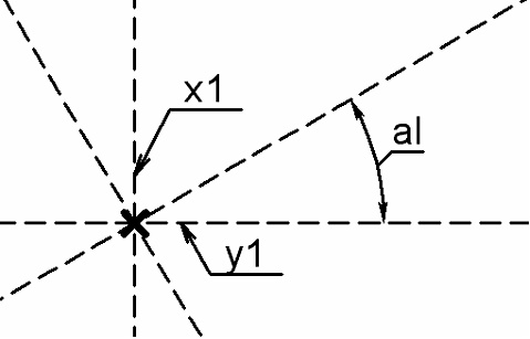
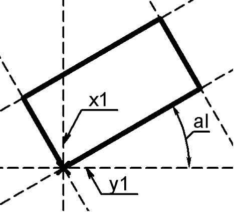
For the convenience of constructing a relatively new coordinate system, it is recommended to perform the following actions. Set the vertical and horizontal lines through the fixing point to "-1" for the level. The straight lines will disappear from the screen, because the visibility level interval from 0 to 127 is set for construction lines in the Set Levels command, and these lines have a level of -1 and do not fall into the interval. After that, call the Document Parameters command, go to the View tab and set the Element Selection parameter to Visible Only. Thus, a mode is set for the drawing in which system elements that are invisible in the drawing will not be selected.
Fragment with two fixing points with the ability to rotate
The specified fragment can be created in two different ways: the first way - when the second fixing point sets the rotation of the fragment and changes the size of the fragment, the second way - when the second fixing point will only set the rotation of the fragment, and its size will not change.
First way:
Create two fixing points of the future fragment. After that, you need to build construction line 1, passing through two nodes - fixing points. This line will define the X-axis of the new local coordinate system of this drawing. To create the Y-axis of a local coordinate system, you need to draw construction line 2, passing through a node and perpendicular to construction line 1. A line drawn through two nodes and a line perpendicular to it define the new local coordinate system of the drawing. All subsequent constructions must be carried out relative to the lines defining the new coordinate system of the drawing. Create line 3 parallel to line 2 and going through the node that defines the second fixing point. Then draw lines 4 and 5, parallel lines 1. After that, you can create the necessary graphic lines.
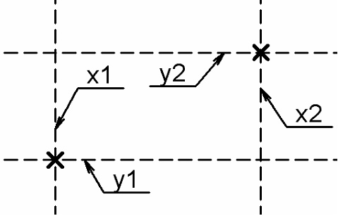
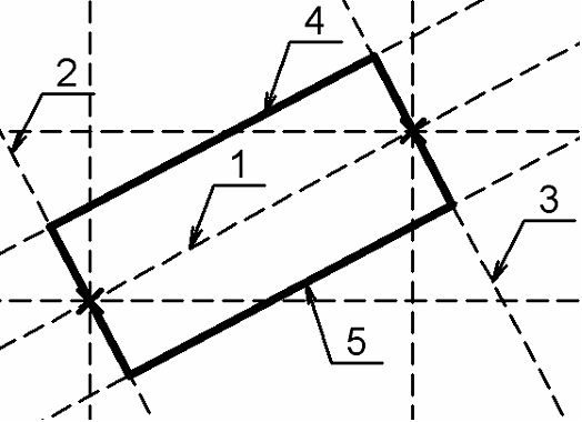
The result is a parametric drawing with two fixing points, the location of which will determine the location of the fragment coordinate system relative to the assembly drawing coordinate system. In addition, the second fixing point will also determine the size of the rectangle.
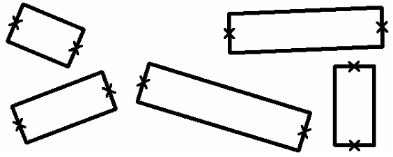
Second way:
All constructions in the second method are completely repeated, except for the creation of line 3, which is drawn parallel to line 2, but is not attached to the node of the second fixing point.
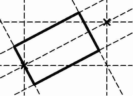
When inserting such a fragment into an assembly, its size will be constant; only the rotation angle of the fragment will depend on the second fixing point.
