Perpendicular Straight Construction Lines through Fragment's Fixing Point |
  
|
The following automenu option is available in the ![]() perpendicular lines creation mode of the
perpendicular lines creation mode of the ![]() Line command:
Line command:
|
<F> |
Create insertion Point for Fragment (xn,yn) |
Activate it, and then create a pair of lines as described in the Perpendicular Lines Using Coordinates section.
In result, the coordinates of the created lines will be defined via two automatically created external variables. Coordinate values specified during lines creation will become values of such variables. Names of variables consist of a letter of a corresponding coordinate (x or y) and an index number. For the fist pair of lines, the variables will be named x1 and y1, for the second pair - x2 and y2, and so on. The index number is displayed near the cursor, when placing the lines. The variables created this way can be used as coordinates of fixing points of the current document, when inserting it into an assembly as a 2D fragment.
After creating a pair of lines, the option is deactivated, so you have to activate it individually for each pair of lines .
The option of creating lines through LCS origin is not compatible with the fixing point creation option.
The maximum allowed number of fixing points in a document is 99. Upon reaching this number, the fixing point creation option becomes non-available.
Example of using fixing points created as intersections of perpendicular construction lines
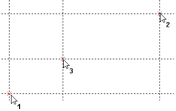
Create three pairs of perpendicular lines, as shown below. Use the fixing point creation option for each pair.
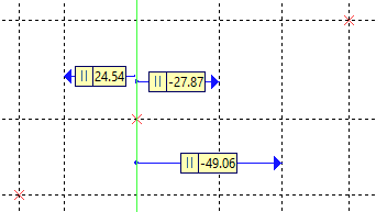
Create three lines parallel to the central vertical one, as shown below/
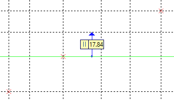
Create a line parallel to the central horizontal one, as shown below.
Create additional connected 2D nodes at intersections, as shown below.
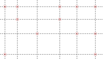
Draw graphic lines, as shown below, using previously created 2D nodes for snapping.
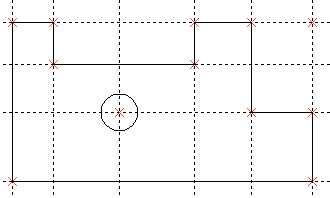
Save the result. Then create a new document, call the ![]() Fragment command and select the previously created drawing as the fragment for insertion. The preview of the fragment will start following the cursor. The 1 number near the cursor means, that you should specify the first fixing point. Place the cursor in the desired position and press
Fragment command and select the previously created drawing as the fragment for insertion. The preview of the fragment will start following the cursor. The 1 number near the cursor means, that you should specify the first fixing point. Place the cursor in the desired position and press ![]() .
.
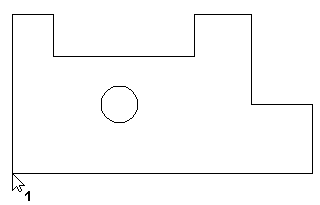
The number near the cursor will change to 2, which means, that now you should specify the second fixing point. Notice, that instead of the whole fragment, only those lines that depend on the second fixing point now follow the cursor. Place the cursor in the desired position and press ![]() again.
again.
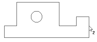
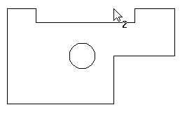
The number near the cursor will change to 3, which means, that now you should specify the third fixing point. Now only the lines depending on the third point follow the cursor. Place the cursor in the desired position and press ![]() once more, in order to finish the fragment insertion.
once more, in order to finish the fragment insertion.

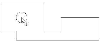
Thus, you can get different configurations of a part by inserting it with different positions of fixing points, without editing the part drawing.