Parameters Dialog of Fixing Vector |
  
|

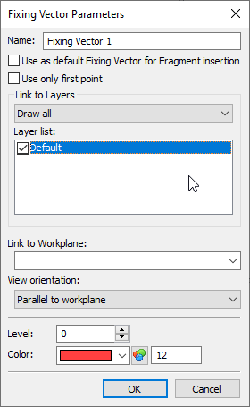
Name. You can set a comment to the fixing vector by which you will distinguish it from others when inserting and editing this drawing as a fragment.
Use as default Fixing Vector for Fragment insertion. Defines the fixing vector that will be offered by default when inserting a fragment into an assembly drawing. Only one main fixing vector can be defined in the fragment drawing, although there can be many fixing vectors.
Use only first point (for fixing vectors defined by a single point). When the flag is set, the first point of the fixing vector is used as the fixing point.
The Link to Layers group is used to define the display of drawing layers when drawing it as a fragment.
It is possible to choose one of three modes for displaying drawing layers when applying it as a fragment:
•Draw all.
•Draw only marked.
•Draw all except marked.
These parameters affect the display of only 2D elements of the fragment. They do not affect the visibility of 3D fragments located on the corresponding layers.
Layer list. This field contains a list of all layers present in the drawing. Here you can mark those of them that will be displayed when drawing a document as a fragment using this fixing vector.
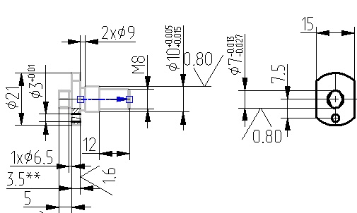
In the figure below, the reference vector and drawing elements that need to be transferred to the assembly drawing are marked with color. These elements have been assigned a new layer. It is this layer that needs to be marked in the fixing vector parameters.
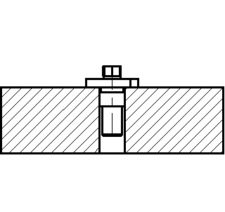
Now, when applying this drawing as a fragment, only the marked layer will be displayed in the assembly drawing, and, therefore, those elements that lie on this layer.


In the context menu for fixing vectors with linked layers, there is the Apply Layer Visibility command. When it is called, the visibility or invisibility of the layers is set in accordance with how they will be displayed when inserting this document as a fragment using this fixing vector.
Link to Workplane. This parameter is relevant only for the 3D version of the system. Serves to define the workplane with which the given fixing vector will be linked. This opportunity is used when creating layouts (see the Creating 2D Representation within Document of 3D Fragment section).
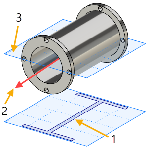
View orientation. The orientation of the view is used when creating layouts (2D fragment on the workplane on a 3D fragment). It allows you to select the condition under which the schematic image will be added to the assembly plane.

1. Assembly workplane
2. Position of the fixing vector
3. 3D fragment workplane
There are three possible options:
•Parallel to workplane;
•Axial symmetry;
•Arbitrary orientation.
Parallel to workplane - after adding the model to the assembly, its schematic image will be created only if the workplane of the assembly is parallel to the workplane in the fragment file with which the vector is associated.
Axial symmetry - Used for models of the body of rotation type. After adding the model to the assembly, its schematic image can be created on any assembly workplane that is parallel to the straight line on which the anchor vector lies.
Arbitrary orientation - It is used for bodies with central symmetry or having the same conditional graphical representation of several types. After adding the model to the assembly, its schematic image can be created on any plane.
Level. Color. These parameters determine the visibility level of the element and the color of its display in the drawing.