Creating 2D Representation within Document of 3D Fragment |
  
|
When creating an assembly drawing, you may use an image (2D representation) specially prepared in a 3D fragment's document, instead of a projection of the 3D fragment.
This can be a simplified image, drawing of a workpiece, schematic designation. This feature can be conveniently used, when creating layouts of industrial shops, electric diagrams and in other cases, that require schematic display of 3D elements on the drawings. In most cases the assembly drawings created using 2D representations are recalculated faster than drawings obtained by projecting the assembly.
Furthermore, 2D representation may be based on a usual 2D projection, but additionally contain graphic elements which can not be obtained by projecting (for example, direction of door opening).
A 2D representation should be created in accordance with special rules described below. Let's explain them using a pipeline element example.
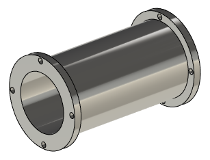
To get started, create a 3D model, as shown above.
Then, on the Top View workplane, create a top view drawing of this element.
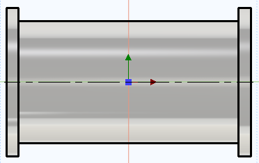
It is important to ensure, that the overall dimensions of the 2D representation and the 3D model are the same. If the model is parametric, then it is also recommended to ensure the automatic regeneration of the 2D representation, when the parameters change.
If you do comply with the aforementioned recommendations, and the length of the pipe's 2D representation, for example, will be less than the length of the 3D fragment, then the 2D fragment will not be connected to other pipeline elements in assembly drawing.
In this case, it is convenient to use the Project Elements command and create the necessary drawing based on auxiliary lines.
You can create several different 2D representations of a part on the same or on different workplanes, and then select any of them when creating an assembly drawing.
When creating multiple 2D representations in the same workplane, you need to assign different layers to different representations.
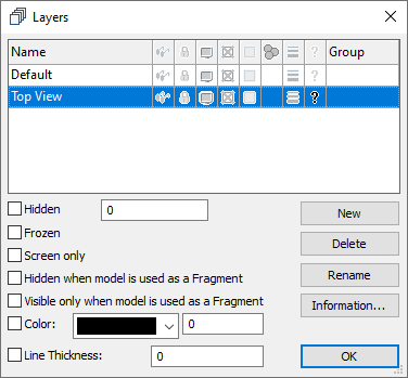
Use the Layers command to create a new Top View layer.
Next, select the graphic lines of the drawing image and select the Top View layer in the parameters window.
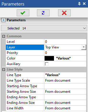
Now the selected graphic lines will be associated only with it.
Next, on top of the previous Top View drawing, create a schematic Scheme drawing using a different color of the graphic lines.
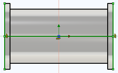
Assign the Scheme layer to the schematic drawing in the same way as described above.
You can control the visibility of graphic lines by enabling the Invisible option for a specific layer.
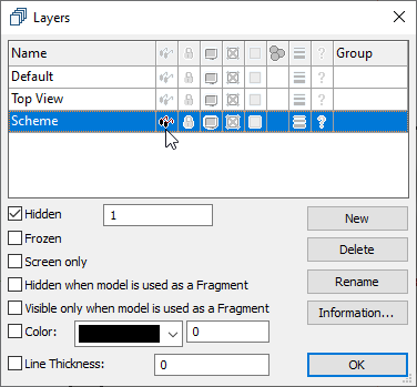
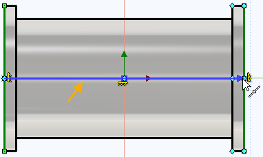
The next step is to create a fixing vector using the Fixing Vector command. Specify the origin and the ending of the vector in the drawing.
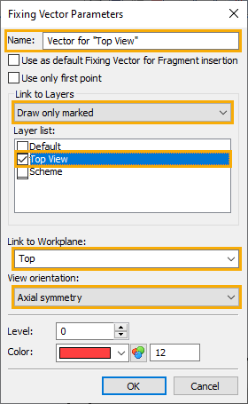
In the vector parameters dialog, specify the name: Vector for "Top View". In the Link to Layers list, select Draw only marked, so that when applied, only the drawing belonging to the selected layer is displayed as a fragment. In the list of layers, enable the checkbox of the Top View layer.
In the Link to Workplane list, select the workplane, to which the fixing vector will be associated. In the View orientation list, select the Axial symmetry option.
Repeat the same sequence of actions for the schematic drawing, specifying a different layer, and save the fragment file.
As a result, when inserting a 2D fragment by 3D fragment of this pipeline element, we'll be able to choose between a standard projection and two custom 2D representations: Top View and Scheme.