Manual Insertion of 2D Fragment by 3D Fragment |
  
|
If there is a custom 2D representation within a document of a 3D fragment inserted into an assembly, then such representation may be inserted as a 2D fragment onto a workplane within such assembly. Moreover, if custom 2D representations are not available for some of the 3D fragments, you may insert onto the same workplane their automatically generated 2D projections using the same mechanism. In both cases the mode of projecting 3D fragments onto workplane is used. This mode may be accessed using the following option, which is available in the automenu after launching the 2D fragment insertion command:
|
<W> |
Project 3D fragments to workplane |
Upon entering the mode, the initial set of automenu options gets replaced by the options described further in this section.
Let's review the mode usage at an example of the pipeline fragment.
Before starting to work on an assembly, you should create 3D model and 2D representations of the pipeline, as described in the Creating 2D Representation within Document of 3D Fragment section.
Then create a new assembly file and insert the previously created 3D pipeline fragment into it.
Next, you need to go to the 2D page of the Top workplane. In order for the pages of the workplanes to be displayed in the 2D window, you need to call the Pages command and enable the Workplane checkbox in the command's dialog.
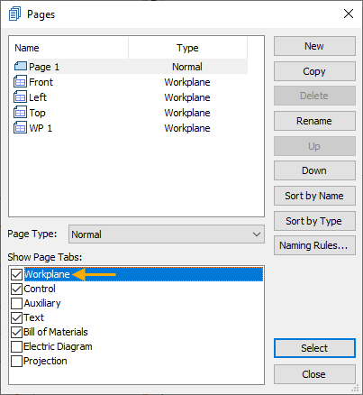
Now workplanes tabs will be displayed at the bottom of the 2D window.

Go to the Top workplane page and call the 2D fragment insertion command.
In order to enter the mode of projecting 3D fragments onto workplanes, activate the following automenu option:
|
<W> |
Project 3D fragments to workplane |
Upon entering the mode, the following automenu option gets activated automatically:
|
<W> |
Select Workplane to set view direction of projection |
Select ![]() the Top workplane. The name of the selected workplane will be indicated in the parameters window.
the Top workplane. The name of the selected workplane will be indicated in the parameters window.
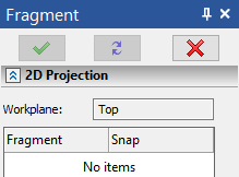
Upon selecting the workplane, the following automenu option gets activated automatically:
|
<F> |
Select 3D fragment |
Select the previously inserted 3D fragment of the pipeline.
It is also possible to select several 3D fragments manually, or select all of the 3D fragments in the 3D scene using the following option:
|
<A> |
Select all 3D fragments in Scene |
The selection may be cleared using the following option:
|
<Esc> |
Cancel selection |
The selected 3D fragments are listed in the parameters window. There is the [...] button for each fragment in the list. Pressing it invokes the drop-down menu, where you can select any of the 2D representations available for the fragment. Names of custom representations in the menu correspond to the names of their fixing vectors.
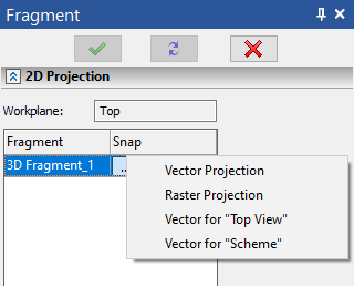
For the current example, following representations are available:
•Vector Projection
The 2D fragment will contain the projection of the 3D fragment using the Precise (Graphic Lines) view style;
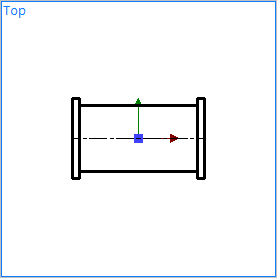
•Raster Projection
The 2D fragment will contain the projection of the 3D fragment using the Shading view style;
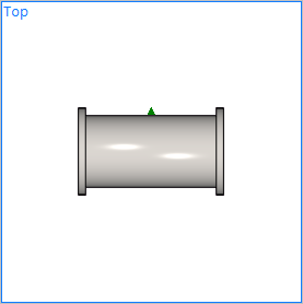
•Vector for "Top View"
The 2D fragment will contain the Top View 2D representation previously created in the document of the 3D fragment;
In the current example this representation looks the same as the automatically generated Vector Projection.

•Vector for "Scheme"
The 2D fragment will contain the Scheme 2D representation previously created in the document of the 3D fragment.
Select the desired representation and finish the input using the following automenu option:
|
<F5>, <Enter> |
Finish input |
The selected 2D representation will be inserted as a 2D fragment onto the selected workplane.
For custom 2D representations, the associative link is kept between the position and orientation of the 3D fragment and its corresponding 2D fragment. However the link only works in one direction - from 3D to 2D. I.e., if you manually move or rotate the 3D fragment in 3D scene, then the 2D fragment will be automatically moved or rotated on the workplane in the same way. However, upon attempting to manually move or rotate the 2D fragment on the workplane, you won't be able to save changes.
For automatically generated 2D representations such associative link only affects the orientation of the fragments. In such cases, the 2D fragment will always be at the origin of the selected workplane's LCS, regardless of the position of the 3D fragment in 3D scene.