Positioning of 2D Fragment |
  
|
Defining fragment placement in the assembly drawing
When specifying location of the fixing vector or fixing points, the nodes of the assembly drawing can be picked for carrying out fragment attachment to the elements of the assembly drawing. When changing location of the specified nodes of the assembly drawing, the fragment placement will be modified as well.
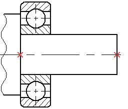
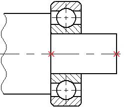
If necessary, the fragment can be inserted by specifying the absolute coordinates for the fixing vector and points. This becomes possible upon clicking at the desired place of the drawing in the absence of object snap. The object snap can be turned off via the toolbar View or by pressing the key <Ctrl> at the time of the click. In this case, with the help of the section Coordinates in the fragment properties window the adjustment of the coordinates of the fragment insertion can be performed.
Fragment placement using fixing vectors
When inserting a fragment by the fixing vector, the system asks to define the vector fixing points.
If the fixing vector was defined in the fragment drawing by a single point, then you need to specify only one point in the assembly drawing to place the fragment. Once that is done, the image of the fragment will be placed in this point. The fragment image cannot be rotated in this case. If the fixing vector was defined by two points in the fragment drawing, then the fragment can be placed in several ways.
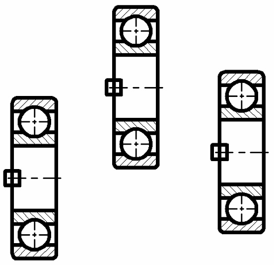
The first way implies specifying two points, the first defining the location of the fragment image, and the second - rotation of the fragment image about the first point.
|
<M> |
Fixing using two points |
When proceeding in this way and snapping the vector start to one node and the vector end to another, modifying the position of the first node will change the location of the fragment image, while the second one - the orientation.

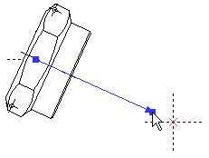
The second approach differs from the first one as follows. The first point still defines the location of the fragment image, while the second point, instead of maintaining the rotation, sets just once the rotation angle of the fragment image with respect to the X-axis of the assembly drawing. The angle of rotation for the fixing vector can be specified as a variable.
This way is handled by the option that appears upon defining the first point:
|
<M> |
Fixing using one point and angle |
With this type of placement, modifications in the position of the first placement node will cause change in the fragment location only, not affecting the rotation angle of the fragment image.

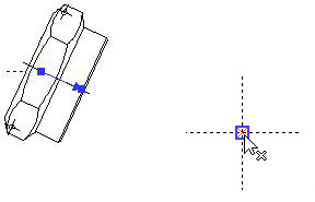
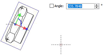
Before confirming the fragment insertion or in the fragment editing command, already inserted points of the fixing vector can be easily changed. For modifying location of the desired point, bring a cursor to this point. The cursor will take the form corresponding to the point number (1 or 2). Next by pressing ![]() select the point, and the system will be ready for modifying the point location. Choose the new position and press
select the point, and the system will be ready for modifying the point location. Choose the new position and press ![]() .
.
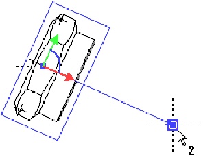
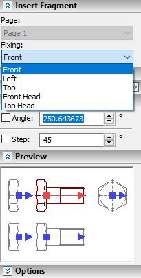
The fragment being inserted can have several fixing vectors. For selecting the desired vector, the section Insert Fragment in the properties window should be used. In the drop down list Page it is possible to select the desired page of the fragment document (if the fragment contains several pages), and then for the selected page the fixing vector is picked in the drop down list Fixing.
The section Preview of the properties window can be also used for changing the fixing vector. Here, on the preliminary image of the fragment, the active fixing vector is highlighted with a red color, the rest are blue. The fixing vector can be selected by clicking in the preview window.
Attaching to connector
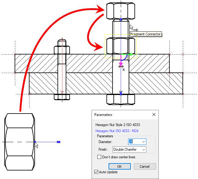
When inserting a fragment with a fixing vector, turn on the mode of snapping to connectors. This mode is activated by the automenu option:
|
<C> |
Mode of snapping to Connectors |
The option appears in the automenu immediately after selecting a fragment file, if the system determines that the current fragment is placed using a fixing vector. In this mode, as the pointer approaches a connector or a graphic line referenced by the connector, the variables of the fragment being inserted automatically assume the values from the same-name connector variables. This reflects on the changing shape of the fragment. At the same time, the updated fragment automatically snaps to the connector.
When attaching to the connector the system may require specifying additional transformations (see below).
If you need to define the values of other variables, this can be done in a conventional way (see above).
Additional transformations
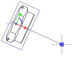
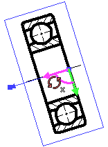
When attaching the fragment with the help of the fixing vector, sometimes it is required to make the fragment location more precise – move or turn the fragment with respect to the axes of the fixing vector, i.e. define additional transformations. Transition to specifying additional transformation can be carried out straightway after specifying the points of the fixing vector. While doing it, a special manipulator in the form of the coordinate system will appear on the fragment image. If the cursor is brought to the elements of the manipulator (the coordinate axes and the arc between the axes), it will be taking the form in accordance with the offered transformation – ![]() ,
, ![]() rotation or
rotation or ![]() ,
, ![]() translation along one of the axes. When specifying the rotation, one of the manipulator's axes is also selected (namely the nearest one) for possibility of defining exact direction to the selected point on the drawing.
translation along one of the axes. When specifying the rotation, one of the manipulator's axes is also selected (namely the nearest one) for possibility of defining exact direction to the selected point on the drawing.
If at this moment ![]() is pressed, the fragment will start moving following the cursor. For fixing the current transformation, it is necessary to select the object on the drawing or specify the numeric value of the transformation. Selection of the object of the drawing will create its associative link with the transformation. This means that upon changing the object location, the transformation will be automatically adjusted as well. The numeric value for the transformation is specified in the properties window or by clicking
is pressed, the fragment will start moving following the cursor. For fixing the current transformation, it is necessary to select the object on the drawing or specify the numeric value of the transformation. Selection of the object of the drawing will create its associative link with the transformation. This means that upon changing the object location, the transformation will be automatically adjusted as well. The numeric value for the transformation is specified in the properties window or by clicking ![]() at the free space of the drawing without selecting the object.
at the free space of the drawing without selecting the object.
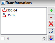
It is possible to define an unlimited number of transformations successively. All specified transformations are put into the properties window. The transformations of similar type (for example, several translations along the same axis) are automatically summed up.
When attaching the fragment to the connectors, the requirement of defining additional transformations can be brought into the fragment file already at the connector creation stage. In this case right away after the connector selection (when attaching another fragment) and reading the values of the variables, the system will automatically turn to specifying the required additional transformation. This approach is frequently used in the libraries of the standard elements since it is not always possible to automatically determine the location of the future fragment. For example, when putting a nut on a bolt, it is almost always necessary to place this nut on the surface being fastened, the attachment to which is specified by a user while defining additional transformations.
Fragment placement using fixing points
If the fragment drawing contains external variables “x1”, “y1”, “x2”, “y2”, etc., then upon inserting the fragment into the assembly drawing you will have to specify as many placement points as you have pairs “x” and “y” with the respective numbers in the fragment drawing.
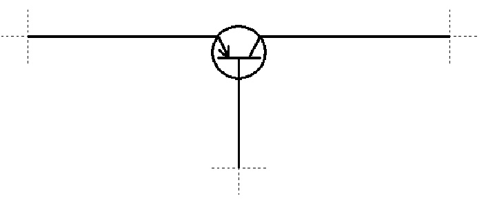
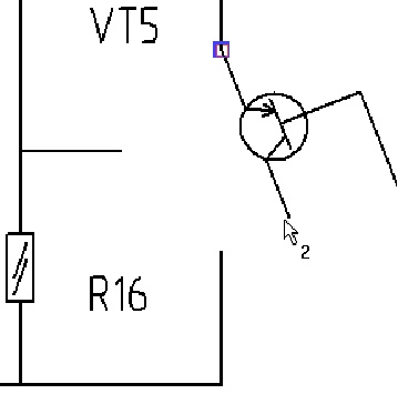
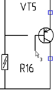
For example, suppose we want to locate the image of the transistor, the drawing of which has three fixing points. Each point specifies location of one transistor contact. When inserting the fragment on the assembly drawing, the system will successively prompt a user to specify location of each point.
When specifying the fragment fixing points, the current fixing point number will be drawn next to the cursor.
The dynamic image following the cursor helps to evaluate the appearance of the future fragment. If necessary (in case of complicated for dynamic imaging fragments) the dynamic image can be switched off with the help of the option:
|
<W> |
Dynamic Preview |
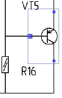
There are two possibilities for specifying locations of the fixing points: attach the fixing point in absolute coordinates (independent of the assembly drawing) or snap to the node on the assembly drawing. Attachment in absolute coordinates is carried out by pressing ![]() while the object snaps are turned off or by pressing simultaneously the key <Ctrl>. Snapping to a node is done via
while the object snaps are turned off or by pressing simultaneously the key <Ctrl>. Snapping to a node is done via ![]() with simultaneous node selection or with the help of the option <N>.
with simultaneous node selection or with the help of the option <N>.