Parameters of 2D Fragment |
  
|
The section Basic Parameters contains data about the fragment file. The text of the link to the fragment file is written in the editable field. The link can be full or relative. The second line displays the full path on the hard disk where the recorded link works. The relative reference can be written manually or automatically in the following form:
•..\..\folder\file_name.grb – in this case, the record is made relative to the file of the assembly drawing. The symbol ..\ denotes going along the folders by one level up with respect the assembly file.
•<library>file_name.grb – in this case, the reference uses the drawings library connected to T-FLEX CAD.
It is recommended to use the relative references which operate in a more flexible way and are not tied to a specific place on the hard disk. It allows a user, for example, to move the assembly with all documents contained in it from one place to another without any losses.
The section Insert Fragment allows a user to select the desired page of the document being inserted as a fragment (parameter Page). This parameter is not available if there is only one page in the fragment. Also, in the drop down list Fixing found in this section, the attachment approach is specified: either by fixing points or by fixing vector.
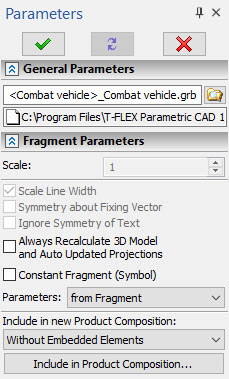
The section Fragment Parameters contains different parameters of the fragment insertion:
Scale. Defines the scale of the fragment being inserted. This is used only when inserting fragments by fixing vectors.
Rotation Angle. Defines the angle of the fragment rotation. This is used only when inserting fragments by fixing vectors.
Scale line thickness. This parameter specifies whether to apply the assigned scale to the fragment lines thickness. This is used only when inserting fragments by fixing vectors.
Symmetry About Fixing Vector. When set, the fragment image will be mirrored about the fixing vector. This is used only when inserting fragments by fixing vectors.
Ignore text symmetry. This parameter is important when using the “Symmetry about vector” flag. When this parameter is enabled, texts on the fragment are not subjected to symmetric reflection with respect to the fixing vector (when the fragment itself is symmetric).
Always Recalculate 3D Model and Auto Updated Projections. With this flag set, the 3D model of the fragment and those of its 2D projections, that have auto update enabled, will be automatically regenerated upon changes in the 2D fragment parameters. This may be useful for updating projections depending on variables of the 2D fragment.
Constant Fragment (Symbol). Setting this parameter makes the inserted fragment saved in the assembly document as a picture. This allows speeding up the work with the assembly since now there is no necessity to resort to external files. The fragment file is not read when opening the assembly. Owing to that, the fragment can be displayed in the assembly even in case its source file is absent. However, since this is a picture, other elements of the drawing cannot be fixed to it. Also, it is not possible to modify variables of such fragment from the variables editor of the assembly drawing (when the connection between the assembly variable and the fragment variable exists). Modifying variables is possible only upon editing such fragment on condition that the source file exists on the hard disk at the indicated reference.
Parameters. As any T-FLEX CAD drawing, a fragment has its own Document Parameters (line thickness, font size, etc.) and Levels visibility intervals. Upon inserting a fragment into an assembly, these parameters may be inherited:
•from Fragment
In this case, parameters specified in the fragment document will be used for displaying the fragment in the assembly.
•from Current Document
In this case, parameters specified in the assembly document will be used for displaying the fragment in the assembly. This option can be used for maintaining a uniform style of assembly drawing. Besides, by changing the ranges of visibility levels in the assembly you can hide or show certain parts of fragments in assembly drawing.
Include in Product Composition.
This parameter manages incorporation of fragment data into the bill of materials of the current drawing. It can take the following values:
•Don’t Include - the fragment is not entered in the BOM table.
•Without Embedded Elements - the fragment is entered in the BOM table. If the fragment is an assembly itself, then only the fragment proprietary data is entered into the BOM. The information about the nested elements (lower-level fragments) is not included.
•With Embedded Elements - the fragment is entered into the BOM together with the nested elements.
•Embedded Elements Only - only the nested elements are entered into the BOM.
If incorporation of fragment data was not defined upon creating a fragment or if it is necessary to associate a fragment with particular Product Composition, you can call the parameters window after the fragment was inserted.
In this case, the name of the aforementioned parameter will change to as Include in new Product Composition and, therefore, this parameter will take effect only on the newly created product composition in the current document.

Additionally, a graphic button Include in Product Composition... will be provided for displaying the window with the list of product compositions existing in the current document, and the settings of the fragment contribution to each of them.
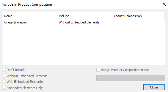
By activating the Assign Product Composition option, one of the structures of the workpiece which are present in the fragment’s file can be selected.
The way of including the given fragment into the assembly’s structure can also be specified using Include in Product Composition command
The section Variables allows a user to specify the values for the fragment external variables.
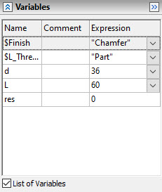
This section is present in the command's properties window only if the fragment being inserted has external variables.
Both the list of variables and the user-defined dialog of the fragment parameters (if it has been created in the document of the fragment being inserted) can be used for specifying external fragment variables. The choice of the desired way to work with the variables is made with the help of the flag List of variables.
The section Coordinates can be used for specifying precise coordinate values for the points of the fixing vector or the fragment fixing points if these points are not being fixed to the elements of the drawing.
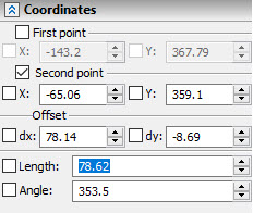
The structure of the controls in the section Coordinates changes depending on the situation.
Section Preview. In this section of the properties window the diminished image of the fragment on the selected page is shown. The fixing vectors are also shown in this window if they exist. The desired fixing vector can be selected in this window by pointing at it. The selected fixing vector is shown with red color. The rest of the vectors are blue.
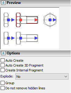
Section Options contains the following parameters:
•Auto create 3D fragment. (Available only for 3D version). If you enable this checkbox, then right away after inserting the 2D fragment the 3D fragment based on the model stored in the 2D fragment's file will be inserted automatically. See more in the Automatic Insertion of 3D Fragment by 2D Fragment section.
•Auto create. When turning on this flag, the process of inserting the fragment will be finished automatically straightway after specifying the fixing points or the points of the fixing vector of the fragment.
•Create internal fragment. This parameter allows a user to create an internal fragment, the contents of which are stored in the assembly drawing, but not in the external file.
Internal fragments cannot be created in T-FLEX DOCs integration mode.
•Explode. As a result of exploding, the drawing view is deleted, while all its content (nodes, graphic lines, etc.) are transferred directly to the drawing page. The operation of the parameter is similar to the Explode Drawing View command in the context menu of the drawing view.
•No. Elements are not transferred.
•Without Constructions. Only the nodes and graphic lines are transferred.
•With Constructions. All construction elements are transferred.
•Group. When a fragment is exploded, all its elements will be automatically combined into a group.
•Do not remove hidden lines. When this parameter is activated, the invisible lines of the fragment will not be deleted.
Priority. Defines the priority of the fragment in the assembly drawing. This is used for changing the order of drawing fragments within the current document and for the fragment hidden line removal. Priority is represented by an integer, positive or negative. Fragments with lower priority will be drawn in the screen prior to the fragments with higher priority. The priority of the current (assembly) drawing is equal to "0" by default.
Level. Sets the fragment level.
Layer. Sets the fragment layer.
The button Options. Provides a shortcut to defining the system parameters for handling fragments. The parameters in this dialog are the same as those on the tab Fragments of the command Set System Options.
See Also: