Top-Down 2D Assembly Design |
  
|
Top-Down 2D Assembly Design |
|
When using the "Top-down" design approach, separate parts-fragments are created directly within the assembly drawing window while working with the assembly. There are two approaches to creating a fragment when using the "Top-down" method - fragment extraction and working in the assembly context. In the first case, a fragment can be created by extracting into a separate file the necessary elements of the assembly drawing, using the Extract Fragment Drawing command. The second case allows creating a new part drawing, using the Create 2D Fragment command, with the provision for referencing existing elements of the assembly drawing.
The fragments created this way can be attached to the elements of the assembly itself or other existing fragments. This helps excluding or significantly reducing use of external variables and simplifies handling of an assembly. Meanwhile, some values of the original model parameters can be obtained directly from the assembly context. This approach significantly simplifies relating elements with each other and provides parametric relation between those. If dimensions or position of one of the parts is modified, then all related model elements will adjust automatically.
Working in the assembly context simplifies in certain cases the design process of the assembly module. This also facilitates development of the complete documentation suite of such a module, including detail drawings of all contributing fragment parts. Upon modifications to any assembly document, either the assembly drawing itself or one of its fragments, the changes propagate to all documents of the assembly (automatically or by the user request). As a result, modifications to one part cause update of the full suite of new documentation for the assembly, including the assembly drawing itself and detail drawings of all contributing part fragments.
The "Top-down" design approach may not be suitable in all cases of designing assemblies. The method has certain shortcomings that limit its use:
•More complicated organization, compared with the approach "from part to assembly";
•Lesser robustness to topology changes. For example, once an assembly line is referenced by an introduced fragment, it can no longer be deleted, otherwise the fragment associative reference will be lost;
•This approach is less convenient in terms of reusing fragments in other assemblies, since modifying a fragment may be complicated without the availability of references to the original assembly;
•Upon an attempt to extract a fragment, if it is impossible to "detach" an element from the assembly drawing, additional copies of the necessary elements are created in order to preserve parametric relations in the assembly drawing;
•Somewhat higher computational resources are required.
Managing fragments in assembly context
When using the option ![]() , the first step will be specifying the name of the fragment being created, using the "Save As" dialog box. After that, all construction elements of the assembly will be hidden in the drawing window, and the graphic elements drawn in halftone. While in this mode, all newly created construction and graphic elements will belong to the new fragment. As you create drawing elements, you can use one of the following modes of snapping to assembly elements:
, the first step will be specifying the name of the fragment being created, using the "Save As" dialog box. After that, all construction elements of the assembly will be hidden in the drawing window, and the graphic elements drawn in halftone. While in this mode, all newly created construction and graphic elements will belong to the new fragment. As you create drawing elements, you can use one of the following modes of snapping to assembly elements:
•Associative snapping.
Can be activated using the following command:
Icon |
Ribbon |
|---|---|
|
|
Keyboard |
Textual Menu |
<FA> |
Customize > Snap > Associative Snap |
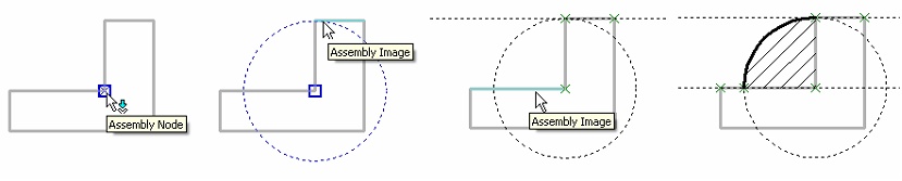
In this case, the fragment elements can be snapped to the graphic lines and nodes of the assembly. (By assembly nodes, we mean the joint points of the graphic lines and the attachment points of the detailing elements.) This ensures two-way relation between the assembly and the fragment file. In other words, changes in the assembly drawing can be propagated, upon the user request, into the fragment file, and, vice versa, modifications in the fragment file cause the assembly document update. As the pointer approaches assembly nodes in this mode, those are highlighted and marked by the tooltip "Assembly Node", while the graphic elements – "Assembly Image".
In order to use associative snapping, you also have to activate non-associative snapping.
•Non-associative snapping.
Can be activated using the following command:
Icon |
Ribbon |
|---|---|
|
|
Keyboard |
Textual Menu |
<FB> |
Customize > Snap > Select Assembly Elements |
The command is also available in the fragment editing toolbar in the top right corner of the view window.
In this mode, snapping to assembly drawing elements is also available. However, in this case, snapping is done to the current "snapshot" of the assembly. The future modifications of the assembly lines won't affect the fragment image.
•No snapping (both of the above modes should be undone). This mode is none different from conventional drafting. The assembly drawing displayed on the screen does not interact with the fragment elements in any ways.
The icons of the snapping modes can be found in the context menu and also in the textual menu “Customize > Snap > ...”.
It should be noted that the inclusion of any of the binding icons is possible only when the system object binding is enabled (View Toolbar > Object Snap).
The following diagrams show fragment creation in the assembly context, using associative snapping. In this mode, the assembly construction elements are hidden, while its graphic lines are shown in the halftone. When creating fragment construction lines, snapping to assembly elements is engaged. The graphic elements of the fragment drawing are created last.
Upon finishing working with the fragment, the system returns to the normal mode of working with the assembly drawing. If the created fragment was saved, its image will appear in the assembly. To finish working with a fragment, use the following commands:
Closes fragment with saving changes.
Closes fragment without saving changes.
Both commands are also available in the fragment editing toolbar in the top right corner of the view window and in the contextual menu invoked by clicking na empty space of the view window with ![]() .
.

Topics in this section:
See Also: