Extract Fragment Drawing |
  
|
Command call:
Icon |
Ribbon |
|---|---|
|
|
Keyboard |
Textual Menu |
<FX> |
File > Fragment > Extract Fragment Drawing |
The command may also be called from the automenu of the existing fragment insertion command using the following option:
|
<G> |
Mark out Fragment |
The command serves for creating a new fragment by moving or copying into a separate file already existing elements of the assembly drawing. Upon the call, the following options appear in the automenu:
|
<Ctrl+Enter> |
Finish Fragment Creation |
|
<M> |
Select Mode |
|
<M> |
Deselect Mode |
|
<F> |
Assign Fixing Vector |
|
<V> |
Select Variables for Copying into Fragment |
|
<D> |
Delete or hide selected elements after creating Fragment |
|
<Esc> |
Exit command |
Fragment extraction is the action opposite to that of the option ![]() Explode Fragment. To create a fragment, the user just needs to select a set of graphic elements (lines, dimensions, hatches, etc.) of the assembly drawing to be carried over into the separate fragment. When creating a fragment, besides the graphic elements picked in the assembly drawing, their respective construction elements are also created.
Explode Fragment. To create a fragment, the user just needs to select a set of graphic elements (lines, dimensions, hatches, etc.) of the assembly drawing to be carried over into the separate fragment. When creating a fragment, besides the graphic elements picked in the assembly drawing, their respective construction elements are also created.
The option ![]() allows picking the assembly drawing elements, adding those to the contents of the fragment. (The selected elements are highlighted.)
allows picking the assembly drawing elements, adding those to the contents of the fragment. (The selected elements are highlighted.)
The option ![]() excludes elements from the selected set.
excludes elements from the selected set.
The option ![]() toggles between the modes:
toggles between the modes:
•If the icon is in the pushed state, then, after creating the fragment, the elements included in the fragment are deleted from the assembly drawing. Exception is the parent elements of other elements. In this case, the system will not delete the element. Instead, it will make it hidden (invisible) by assigning a special attribute;
•If the icon is not pushed, then the fragment contents are formed by the copies of the selected elements.
Creation of a fixing vector (the option ![]() ) is optional. However, if you need to make a provision for modifying the attachment of the fragment being created or placing its duplicate at other locations, then you should perform this step. A fixing vector can be created in one of the ways described above.
) is optional. However, if you need to make a provision for modifying the attachment of the fragment being created or placing its duplicate at other locations, then you should perform this step. A fixing vector can be created in one of the ways described above.
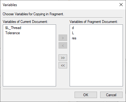
The option ![]() brings up the dialog box for selecting variables existing in the assembly drawing, to be copied to the fragment. The list in the left-hand side pane contains all plain variables. Variables defined by an expression cannot be copied into a fragment. The variables can be carried from the left to the right pane and back using the graphic buttons [>], [<]. The buttons [>>], and [<<] allow carrying over the whole list. All fragment variables that originated from the assembly drawing are automatically deemed "external".
brings up the dialog box for selecting variables existing in the assembly drawing, to be copied to the fragment. The list in the left-hand side pane contains all plain variables. Variables defined by an expression cannot be copied into a fragment. The variables can be carried from the left to the right pane and back using the graphic buttons [>], [<]. The buttons [>>], and [<<] allow carrying over the whole list. All fragment variables that originated from the assembly drawing are automatically deemed "external".

The fragment creation can be completed using the icons:
|
<End> |
Finish Fragment Creation |
|
<Esc> |
Exit command (without saving the fragment) |
Calling the option ![]() brings up the dialog box for defining the fragment filename. If variables to be copied to the fragment were not defined in the course of the fragment creation (as they would have been by the option
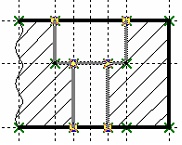
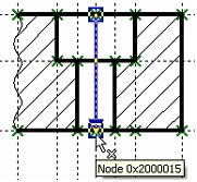
brings up the dialog box for defining the fragment filename. If variables to be copied to the fragment were not defined in the course of the fragment creation (as they would have been by the option ![]() ), the dialog for selecting variables will appear prior to the filename defining dialog. The diagrams on the right hand side show the fragment extraction. The first step is selecting the elements to include in the new fragment.
), the dialog for selecting variables will appear prior to the filename defining dialog. The diagrams on the right hand side show the fragment extraction. The first step is selecting the elements to include in the new fragment.


After that, a fixing vector is created. Next, the necessary variables are selected, and the filename is defined. As a result, the selected lines are placed in the assembly drawing by the 2D fragment possessing the set of the specified parameters.
Whenever possible, we recommend creating all elements directly in the new fragment, rather than carrying those over from the assembly drawing. This approach enhances productivity.