Parameters Dialog of 3D Fragment |
  
|
Detailed setting of many parameters for a 3D fragment can be accomplished at any moment in the parameters dialog box. It is called using the following automenu option of fragment's creation , and editing commands, as well as from the contextual menu of fragment operation:
|
<P> |
Set entity parameters |
The dialog contains following tabs:
•Degrees of Freedom
This tab is available, only if degrees of freedom are specified in parameters of fragment's source or target CS.
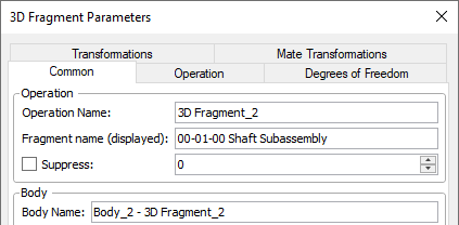
This tab contains the parameters common for 3D elements of various types.
Unlike operations of other types, for 3D fragments the Operation group of parameters at the top of the tab contains the Fragment name (displayed), in addition to the Operation Name. These names depend on parameters of fragment's document. The detailed information on how the system assigns and uses these names is available in description of document parameters. Moreover, for 3D fragments the Operation Name is added to the Body Name.
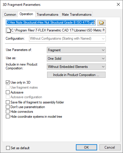
Configuration. If there are configurations in the fragment document, then this parameter allows you to select from the list of configurations the one that will be used for this part. By default, the value is set to Without Configuration. For parts created in the context of an assembly, this option is not available.
Use Parameters of defines the source of the fragment parameters specified in the Set Document Parameters command.
•Fragment. The fragment parameters will be taken from the fragment file.
•Current Drawing. The fragment parameters will be taken from the current document file.
Use as. This parameter can take one of the two values: One Solid or Separate Solids. With the value Separate Solids used, the additional operation Divide is applied for dividing the fragment into the separate bodies. This is necessary in the cases when the 3D fragment itself is made of several bodies, while just one of them should be used, for instance, in a boolean operation with another assembly element. It will be impossible to select a particular body of the 3D fragment without dividing into separate bodies. Instead, you will be always getting the whole operation 3D Fragment selected as one object. The operation Divide can also be done manually after inserting the 3D fragment, with the same result.
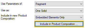
Include in new Product Composition. In the field, you can set the conditions for including a fragment in the product composition. The parameter controls the entry of information about the fragment into the assembly product. It can take the following values:
•Don't Include - the fragment is not included in the product composition.
•Without Embedded Elements - the fragment is entered into the product composition. If the fragment is an assembly unit, then only information about the fragment is entered into the product composition. Information about embedded elements (lower-level fragments) is not entered.
•With Embedded Elements - the fragment is entered into the product composition together with the embedded elements.
•Embedded Elements Only - only embedded elements are entered into the product composition.
If the method of inclusion in the product composition was not specified when applying the fragment, or it is necessary to establish a connection with the specific composition of the assembly drawing for the fragment, then the dialog box for the parameters of this fragment can be called after the fragment has been inserted into the assembly.
To do this, click the Include in Product Composition button, which displays a window with a list of existing product compositions in the current document and the parameters for including a fragment in each of them.
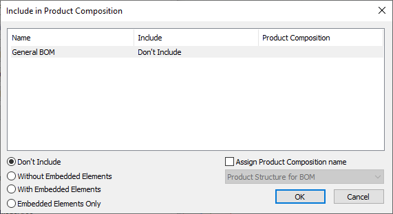
If necessary, you can select any product composition from the list and change the value of the parameter responsible for the inclusion of the fragment. When the Assign Product Composition name flag is set, you can select the fragment product composition, the data from which will be included in the assembly product.
You can also specify how to include this fragment in the assembly using the Include in Product Composition command.
Use only in 3D. If you disable this checkbox, a 2D fragment based on the image stored in the 3D fragment's file will appear in the model tree. See more at the Automatic Insertion of 2D Fragment by 3D Fragment section.

This 2D fragment will not be visible until the fragment editing command is called. After calling the command, the system will warn that a 2D window will be opened and switch to editing mode. Further actions are performed according to the description given in the Inserting Fragments into a Drawing section.
Use fragment mates. When a different assembly unit, in which the mates have been created and the degrees of freedom have already been defined, is inserted into the assembly, there is a possibility to transfer the entire mechanism into the new assembly by using only operation of insertion of a 3D fragment. To insert such fragment-mechanism into the assembly, the option of using the fragment As Separated Bodies and the option Use fragment mates have to be turned on simultaneously.
Autosave. When changing the values of external variables of the fragment in the assembly the fragment’s file is resaved according to the new values. The fragment’s file is updated at the moment of saving the assembly file. This flag can be conveniently used for obtaining detail drawings. If projections are used in the file of the fragment, then for their recalculation during autosaving the mode of automatic update must be selected in the projection’s parameters.
Autosave configurations. This parameter allows you to save configurations automatically.
Save file of fragment to assembly folder. If this flag is enabled, then next to the assembly file the folder is created, which has the name of the assembly file, and the fragment’s file is saved into the folder. The relative path for the fragment is created.
Do not use parameterization. When this flag is enabled, external variables of the fragment cannot be changed. The Variables window is not invoked from the context menu of the fragment and does not appear during the fragment editing.
Hide connectors. When this flag is enabled connectors of the fragment are not shown in 3D scene and in the tree of a 3D model.
Do not show coordinate systems in the tree of a model. When this flag is enabled external coordinate systems of the fragment are displayed in 3D scene, but are not shown in the tree of a 3D model.
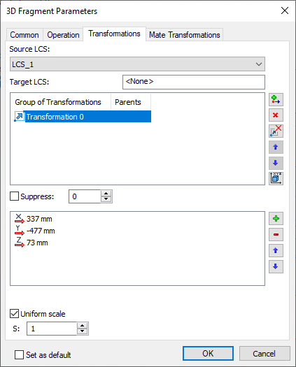
Via the Transformations tab, it is possible to work with list of all geometric transformations which have been applied to the given operation of a 3D fragment. Among those, there could be:
•additional transformations defined upon creating or editing 3D fragment;
•transformations, assigned in the command Transform Element;
•transformations for the Exploded View mode;
•specific service transformations for performing the functions of attaching a 3D fragment.
Any transformation can be applied either permanently or only in the special mode of exploded view for the assembly. This is controlled by the corresponding flag in the settings of each transformation.
3D fragments and Parts can be subject to a special type of a transformation called Attachment. Instead of somehow transforming the body of a 3D fragment in the space, this type of transformation merely defines the attachment by the coordinate systems. This transformation is introduced automatically by the system upon inserting each 3D fragment. Its name depends on the attachment type of the 3D fragment:
•Fix by Fragment LCS - is the 3D fragment attachment transformation in which the fragment LCS was used as the source coordinates.
•Fix by Assembly LCS - is the 3D fragment attachment transformation in which the source coordinate system was created on the fly in the transparent mode when inserting the 3D fragment.
•Fix by Workplane - is the 3D fragment attachment transformation in which the attachment is defined by the 2D fragment (layout).
When suppressing the transformation defining a 3D fragment attachment, the fragment model is positioned in the scene by coinciding the global coordinate system of the fragment with the global coordinate system of the assembly.
To disable any transformation, set the flag Suppress in its parameters. The input box next to the flag check box allows entering numerical values or non-textual variables. The transformation is considered suppressed whenever the entered expression is not equal 0.
3D fragments possess another special type of transformation, providing for the automatic 3D fragment exploding data copying from the parameters of its source coordinate system. The respective chapter about local coordinates reads: if you plan to use a given LCS as the source coordinates for attaching a 3D fragment, then you can define, among its parameters, the necessary translation/rotation for future exploding. This transformation is called Source LCS Transformation. It only becomes available, when the source LCS of the 3D fragment actually has those parameters defined. Such transformation cannot be modified in any way.
A special Apply exploded view transformation of base elements flag allows exploding a given 3D fragment with respect to its fixing point, accounting for exploding transformation of the base elements. That means, turning on the flag additionally moves the fixing point of this 3D fragment per the transformation of the base element.
The Uniform Scale flag is located at the bottom of the window, which allows you to adjust the scale of the fragment. If this flag is set (by default), then one field M is displayed to set the numerical value of the fragment scale, which is applied simultaneously on all axes. If the flag is unchecked, then instead of the above field, three fields X, Y and Z are displayed to set individual values of the fragment scale on each axis.
See Also: