Global Coordinate System |
  
|
Global Coordinate System (GCS) is a coordinate system used by default for calculating positions and orientations of all 3D elements in current document. GCS is an integral part of any document. It is not displayed in the list of model elements and in 3D scene, but it is available for selection in some 3D elements creation and editing commands.
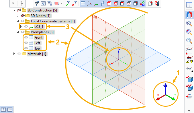
Direction of GCS axes is indicated in the bottom right corner of 3D window. The size of the indicator can be customized in system options (![]() Options > 3D > Size of coordinate system > Scene).
Options > 3D > Size of coordinate system > Scene).
Documents created from 3D prototypes contain three standard workplanes by default. These planes are parallel to GCS planes (Front workplane - to XZ plane, Left workplane - to YZ plane, Top workplane - to XY plane). Default color of standard workplane corresponds to color of GCS axis parallel to a normal direction of such workplane (Front workplane - Y axis - green color, Left workplane - X axis, red color, Top workplane - Z axis - blue color). The normal direction of workplane may have the same direction, as the GCS axis, or an opposite direction, depending on document parameters (Document parameters > Document > 3D > Workplanes > 3D Triad Orientation). The intersection point of standard workplanes coincides with the GCS origin by default. You can move, delete or manually create such workplanes, if necessary. In addition to the standard workplanes mentioned above, similar planes with opposite normals can be created - Back, Right, Bottom. Standard view points and standard 2D projections are available, regardless of presence or absence of corresponding standard workplanes in 3D model.
By default, view directions of standard view points and projecting directions of corresponding standard 2D projections are opposite to normals of eponymous standard workplanes, because the GCS is selected as main view coordinate system in document parameters (Document Parameters > Document > 3D > 3D > Main View Coordinate System). However, selecting a different main view coordinate system doesn't affect standard workplanes, as they're always defined by the GCS. Standard view points and 2D projections are available, regardless of the presence of eponymous workplanes in 3D model.
Instead of GCS, ![]() Local Coordinate Systems (LCS) can be used for calculating particular 3D elements.
Local Coordinate Systems (LCS) can be used for calculating particular 3D elements.

1 - Indicator of global coordinate system axes direction
2 - Standard workplanes
3 - Local coordinate system coincident with the global one
See Also: