Standard Workplane |
  
|
The command can be called in one of the following ways:
Icon |
Ribbon |
|
3D Model > Construct > Standard Workplane Support Geometry > Worksurfaces > Standard Workplane |
Keyboard |
Textual Menu |
<3DS> |
|
Automenu of the |
|
<S> |
Standard Workplane |
This command allows you to create a standard workplane or a set of standard workplanes. Standard workplane is a workplane parallel to one of the planes of the global coordinate system (GCS).
Standard workplanes creation modes
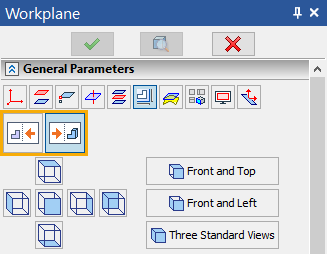
Using the buttons in the parameters window, you can switch between the following modes of standard workplanes creation.
![]() Standard Workplane on 2D Drawing
Standard Workplane on 2D Drawing
![]() Standard Workplane in 3D Window
Standard Workplane in 3D Window
The desired mode must be enabled before selecting a specific view of standard workplane.
In order to create a standard workplane, you should specify its view. View defines a plane of the global coordinate system (GCS), which the resulting workplane will be parallel to. Normal direction of a workplane and orientation of workplane's LCS depend on the 3D triad orientation specified in document parameters (Document parameters > Document > 3D > Workplanes > 3D Triad Orientation). Upon changing the 3D triad orientation, normal directions and LCS orientations of previously created standard workplanes flip automatically. Options for creating multiple standard workplanes at once may yield different results, depending on the workplanes standard selected in system options (Options > 3D > Workplanes > Standard). Following views are available:
![]() Front View
Front View
The resulting workplane is parallel to the XZ plane of the GCS.
The 3D triad orientation is set to ISO by default, so the normal direction of the resulting workplane coincides with the direction of the Y axis of the GCS. Upon changing the 3D triad orientation to ANSI, the normal direction of the resulting workplane becomes opposite to the direction of the Y axis of the GCS.
![]() Back View
Back View
The resulting workplane is parallel to the XZ plane of the GCS.
The 3D triad orientation is set to ISO by default, so the normal direction of the resulting workplane is opposite to the direction of the Y axis of the GCS. Upon changing the 3D triad orientation to ANSI, the normal direction of the resulting workplane becomes coinciding with the direction of the Y axis of the GCS.
![]() Top View
Top View
The resulting workplane is parallel to the XY plane of the GCS, the normal direction of the resulting workplane coincides with the direction of the Z axis of the GCS, regardless of the 3D triad orientation. If the 3D triad orientation is set to ANSI, directions of axes of the resulting workplane's LCS coincide with directions of eponymous axes of the GCS, otherwise - don't coincide.
![]() Bottom View
Bottom View
The resulting workplane is parallel to the XY plane of the GCS, the normal direction of the resulting workplane is opposite to the direction of the Z axis of the GCS, regardless of the 3D triad orientation.
![]() Left View
Left View
The resulting workplane is parallel to the YZ plane of the GCS.
The 3D triad orientation is set to ISO by default, so the normal direction of the resulting workplane coincides with the direction of the X axis of the GCS. Upon changing the 3D triad orientation to ANSI, the normal direction of the resulting workplane becomes opposite to the direction of the X axis of the GCS.
![]() Right View
Right View
The resulting workplane is parallel to the YZ plane of the GCS.
The 3D triad orientation is set to ISO by default, so the normal direction of the resulting workplane is opposite to the direction of the X axis of the GCS. Upon changing the 3D triad orientation to ANSI, the normal direction of the resulting workplane becomes coinciding with the direction of the X axis of the GCS.
![]() Front and Top
Front and Top
Two planes are created at once. The workplanes standard is set to ISO (First Angle) by default, so this option creates Front and Top workplanes. If you change the workplanes standard to ANSI (Third Angle), this option will create Front and Bottom workplanes (see above).
![]() Front and Left
Front and Left
Two planes are created at once. The workplanes standard is set to ISO (First Angle) by default, so this option creates Front and Left workplanes. If you change the workplanes standard to ANSI (Third Angle), this option will create Front and Right workplanes (see above).
![]() Three Standard Views (available in 3D only)
Three Standard Views (available in 3D only)
Three planes are created at once. The workplanes standard is set to ISO (First Angle) by default, so this option creates Front, Left and Top workplanes. If you change the workplanes standard to ANSI (Third Angle), this option will create Front, Right and Bottom workplanes (see above).
View directions of standard view points and projecting directions of corresponding standard 2D projections are opposite to normals of eponymous standard workplanes by default, because the global coordinate system is selected as main view coordinate system in document parameters (Document Parameters > Document > 3D > 3D > Main View Coordinate System). However, selecting a different main view coordinate system doesn't affect standard workplanes, as they're always defined by the GCS. Standard view points and 2D projections are available, regardless of the presence of eponymous workplanes in 3D model.
Creating standard workplane in 3D window
Upon calling the command, enable the ![]() Standard Workplane in 3D Window mode and select a desired view.
Standard Workplane in 3D Window mode and select a desired view.
After selecting a view, a preview of the resulting workplane will automatically appear in the 3D scene.
By default the position of the workplane and the origin of its local coordinate system is determined by the origin of the global coordinate system. Alternatively you can change position using Link with 3D Node. Then the workplane's origin coincides with selected node.
Confirm the workplane creation by clicking the ![]() button.
button.
Editing standard workplane in 3D window
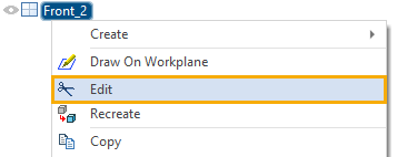
Click ![]() on an existing workplane and select the Edit option in the contextual menu.
on an existing workplane and select the Edit option in the contextual menu.
The Parameters window will contain options for establishing a projection link between the selected workplane and other elements of the model.
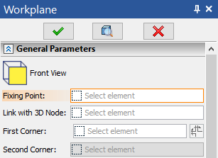
The system will offer to select a 2D node (Fixing point option) belonging to the image located on the new workplane, which will be the origin point of this view. Fixing point selected in 2D window is the projection of 3D node selected in 3D window for the Link with 3D Node option. If Link with 3D node is not defined, the fixing point is the projection of the global coordinate system origin. After selecting a 2D node as a fixing point, the system will automatically select the same node as the First Corner of the border.
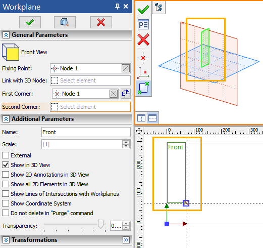
If this is not necessary, then you can reset the selection of the first corner of the border:
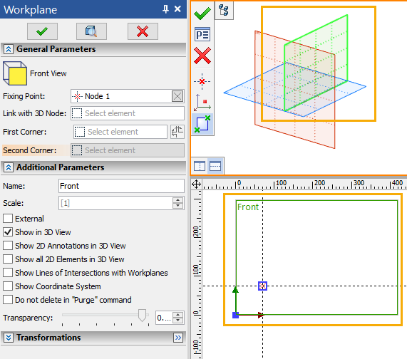
If necessary, you can change or define the Link with 3D Node option.
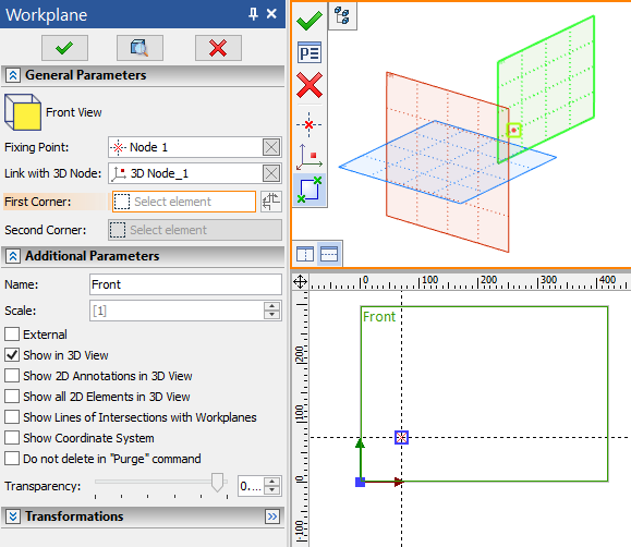
You can also redefine the boundaries of the new standard workplane by selecting two 2D nodes (First/Second Corner options). By default, the boundaries of the workplane are determined by the 2D node selected in the first step and the closest corner point of the drawing boundaries (Front View - top left, Bottom View - bottom left, Left View - top right).
If only the 2D node defining the first corner of the border is selected, you can change the direction of the border of the workplane using the ![]() Switch Workplane Borders button. When the button is pressed, the border will change its direction clockwise from the node.
Switch Workplane Borders button. When the button is pressed, the border will change its direction clockwise from the node.
Workplane boundaries can be used to select a workplane when constructing 3D elements and to determine whether 2D elements belong to a specific workplane.
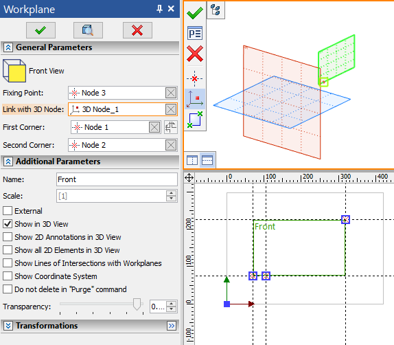
Press ![]() to confirm the creation of a new standard workplane. If the 3D node is not selected, the system will consider the 2D node selected at the first step as the projection of the origin point (0, 0, 0).
to confirm the creation of a new standard workplane. If the 3D node is not selected, the system will consider the 2D node selected at the first step as the projection of the origin point (0, 0, 0).
ANSI or ISO standard selected in the System Options 3D tab only affects the set of workplanes.
Creating workplane from a 2D drawing
Upon calling the command, enable the ![]() Standard Workplane on 2D Drawing mode and select a desired view. The Three Standard Views option is not available in 2D.
Standard Workplane on 2D Drawing mode and select a desired view. The Three Standard Views option is not available in 2D.
If one workplane is created in the 2D drawing window, and there are no other workplanes on the current drawing page, then the workplane will occupy the entire working area of the drawing and the system will offer to establish a projection link between the new standard workplane and the already created workplanes, i.e. select a Fixing Point, set Link with 3D Node and select the First and Second Corners of the border in the same way as for editing a ready-made workplane (see Editing standard workplane in 3D window).
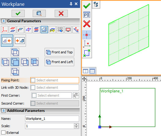
If two workplanes are created in the 2D view window, the system will offer to select a 2D node as the Origin of workplane's LCS.
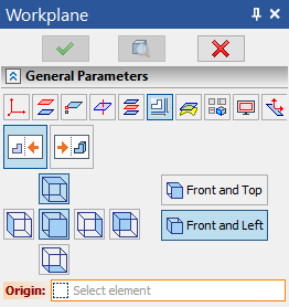
In this case, the result will look like this:
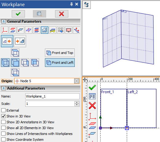
As you can see above, when you create two workplanes in the 2D window, they will be located on the same drawing page. In this case, they cannot be used in active workplane mode.
Additional Parameters are described in the corresponding section.
Sequence of creation
1. Call the command Standard Workplane.
2. Select the view in which you will create the workplane - Standard WP on 2D drawing or Standard WP in 3D window.
3. If you have selected the mode of creating WP in 3D window, then you need to select the desired views and, optionally, Link with 3D Node.
If you have selected the mode of creating WP on 2D drawing, then you need to select the desired views, define the fixing point and, optionally, Link with 3D Node and Corners of the border
4. Customize additional parameters if necessary.
5. Confirm the creation of the workplane.
See Also: