Workplane |
  
|
Calling the command:
Icon |
Ribbon |
|---|---|
|
3D Model > Construct > Workplane Draw > 3D Model > Workplane Assembly > Construct > Workplane Sheet Metal (3D) > Construct > Workplane Surface > Construct > Workplane Weld > Construct > Workplane Primitives > Construct > Workplane |
Keyboard |
Textual Menu |
<3W> |
Construct > Workplane |
The command is intended for constructing workplanes, which are the initial elements for creating auxiliary 3D elements.
In addition, workplanes are used as construction elements in many 3D operations. For example, they can be used to set the cutting plane of the body in the Cut operation or the position of the cutting plane when creating a section. The normal to the working plane can be determined by the direction of extrusion or the axis of rotation, etc.
The system provides mechanisms that make it possible to speed up the creation of workplanes and drawing on them: creating workplanes in transparent mode, creating planes parallel to existing work planes using special manipulators, drawing directly in the 3D scene in the active workplane mode.
Available types of workplanes creation:
|
<L> |
|
|
<1> |
|
|
<3> |
|
|
<7> |
|
|
<E> |
|
|
<S> |
|
|
<8> |
|
|
<J> |
|
|
<9> |
|
|
<2> |
A distinction should be made between workplanes created in 2D and in a 3D window. The position of the workplanes in three-dimensional space is determined either by the world coordinate system (standard workplanes), or by the elements of the 3D model. When created in the 2D view window, the workplane is snapped to the elements of the 2D drawing. Each working plane specified in the 3D window is assigned a separate drawing page, and the working plane specified in the 2D window occupies a certain area on the current drawing page. If more than one workplane is located on one page, then these workplanes cannot be used to work in the active workplane mode.
Note that although the boundaries for the workplanes are indicated in the 3D view window, they are used only for displaying the workplanes. In reality, the workplanes are infinite.
The outer boundaries of the workplane in the 3D window are drawn with a solid line, and the inner lines - with a thin dashed line. The size of the visual boundaries of all workplanes created without reference to 2D constructions can be changed using the size manipulators that appear when you click on the required workplane.
When you change the visual boundaries of the workplane, the boundaries of the 2D page created for this workplane will also change.
If you move the cursor to the lines of the plane, it will be highlighted. By pressing ![]() , the plane can be selected for any actions, and by pressing
, the plane can be selected for any actions, and by pressing ![]() - call the context menu for it.
- call the context menu for it.
You can also select a workplane in the 3D model tree, in the Workplanes folder, or in the part of the tree that illustrates the history of the creation of any 3D element based on the workplane.
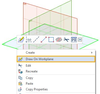
Let's say that you want to create a 3D profile on the workplane Top View, which will serve as the basis for creating a 3D body.
To do this, press ![]() on the Top View workplane in the 3D window or model tree. In the context menu that appears, select the Draw on Workplane item.
on the Top View workplane in the 3D window or model tree. In the context menu that appears, select the Draw on Workplane item.

Topics in this section:
•Manipulators for Editing Workplane without Calling Commands
•Manipulators of Workplane's Drawing Side
•Display of Workplane in 3D Window
•Size and Position of Workplane