Workplane between Two Planes |
  
|
The command can be called in one of the following ways:
Icon |
Ribbon |
|
Support Geometry > Worksurfaces > Workplane between two planes |
Keyboard |
Textual Menu |
<3KSS> |
|
Automenu of the |
|
<E> |
Between Two Planes |
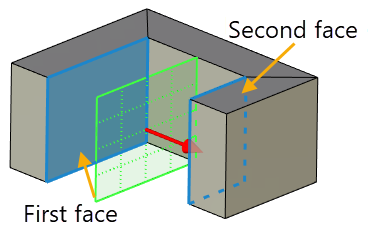
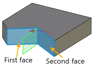
This command allows you to create a workplane between two planes or faces.
The result depends on whether selected planes/faces are parallel to each other and on the Factor value. Default Factor is 0.5. Factor value can be changed in the command parameters window or in the 3D scene using the manipulator.
Parallel planes
If original planes are parallel, resulting plane is also parallel to them. Distance between first original plane and resulting plane is equal to distance between original planes multiplied by Factor. Positive values are applied in direction from first original plane to second; negative - in reverse. Factor's sign can be changed using the ![]() Reverse button.
Reverse button.
Therefore:
If Factor value is equal to zero, resulting plane coincides with first original plane.
If Factor value is equal to one, resulting plane coincides with second original plane.
If Factor value lies between zero and one, resulting plane splits distance between original planes in proportion corresponding to factor.
If Factor value is less than zero, resulting plane lies by the same side of both original planes. Distance between resulting plane and nearest (first) original plane is equal to distance between original planes multiplied by Factor's absolute value.
If Factor value is higher than one, resulting plane lies by the same side of both original planes. Distance between resulting plane and nearest (second) original plane is equal to distance between original planes multiplied by difference between Factor and one.
After selecting two parallel planes it is becomes possible to select Point.
Selecting a point affects position of resulting plane in the following way. A plane parallel to original planes is created through selected point and then being offset using distance between original planes multiplied by Factor.

Non-parallel planes
If original planes are not parallel, angle between first original plane and resulting plane is equal to angle between original planes multiplied by Factor.
By default positive values are applied in direction of the shortest turn from first original plane to second; negative - in reverse. Directions of positive and negative values can be swapped using the ![]() Reverse button. Unlike parallel planes mode, using the Reverse button doesn't affect Factor's sign.
Reverse button. Unlike parallel planes mode, using the Reverse button doesn't affect Factor's sign.

Additional Parameters are described in the corresponding section.
Sequence of creation
1. Call the command Workplane between Two Planes.
2. Select first plane.
3. Select second plane.
4. Select point (optional).
5. Set the factor (optional).
6. Set the workplane coordinate system (optional).
7. Customize additional parameters if necessary.
8. Confirm the creation of the workplane.