Workplane Parameters |
  
|
Additional Parameters of workplane
When creating workplanes, the Parameters window always contain the Additional Parameters tab. It contains same parameters for all workplane types with a few exceptions. Parameters common for all workplane types are described below. Workplane type specific parameters are described in sections describing the particular type.
Name. You can type in a custom name for a workplane or leave default name unchanged. Detailed information about default names can be found in the Names Customization for 3D Elements chapter.
Scale. Defines scaling of elements created when drawing on this workplane. E.g.: "5" value means scale 1:5; "0.5" value means scale 2:1.
Suppress. Enabling the checkbox excludes the workplane from the model and sets the "1" value in the corresponding input box. Disabling the checkbox includes the workplane into the model and sets the "0" value in the corresponding input box. Value may also be typed manually or defined by a real variable for controlling the suppression via Parametrization. Workplane is suppressed if a variable's value isn't zero. Suppressed workplane isn't displayed in the 3D scene.
External. Enabling this checkbox allows displaying of a workplane in assemblies when inserting the current file as a fragment.
Show in 3D Window. If the checkbox is enabled, the visibility of the workplane in 3D windows can be managed using special commands. If the checkbox is disabled, the workplane is not displayed, and not affected by elements visibility control commands.
Show 2D Annotations in 3D Window. Enabling this checkbox makes drawing annotation (detailing) elements (dimensions, symbols, texts etc.), that were drawn on that workplane, visible in the 3D window outside drawing on workplane mode. So you can edit them without entering the drawing on workplane mode.
Show all 2D elements in 3D Window. Enabling this checkbox makes all hatches, graphic lines and other 2D image elements, that were drawn on that workplane, visible in the 3D window outside drawing on workplane mode.
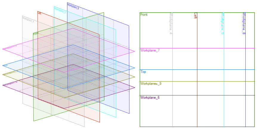
Show intersection lines with workplanes. When the checkbox is enabled, not only workplane boundaries but also intersection lines with the other model workplanes will be shown.

Intersection lines can be used as a reference for creating graphic lines.
Three checkboxes mentioned above are also available in workplane's contextual menu.

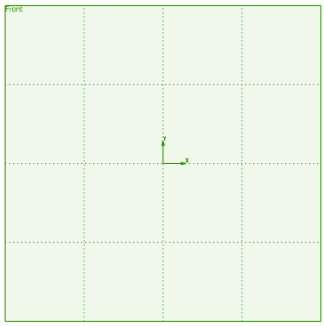
Show Coordinate System. This checkbox controls the display of the workplane's own coordinate system on its rectangle in the 3D scene. By default, this checkbox is disabled, i.e., the coordinate system is not displayed.

Do not delete in "Purge" command. When the checkbox is enabled the workplane will not be deleted, even if it is not used for the operations creation.
Transparency. This parameter allows a user to control the transparency level for the workplane's rectangle in the 3D window.
Name Font Size. Size of font in which name of workplane is displayed in left upper corner of its rectangle in 2D and 3D windows.
Existing workplane parameters dialog
Parameters in Transformations and Mate Transformations tabs as well as some of parameters in the Workplane tab and Set as default checkbox work in the same way for all 3D construction types. Detailed information about such parameters can be found in the Parameters Dialog of 3D Construct section.
The Workplane tab of the parameters dialog also contains same parameters as the Additional Parameters tab of the command Parameters window when creating a new workplane. Such parameters are described above.
The Type dropdown list is present in parameters dialog for all types of workplanes. However it can be edited for standard workplane and workplane based on LCS. There you can change orientation of workplane in relation to custom or global CS. E.g.: change Left view to Right view or XY to XZ.
Parameters dialog for some types of workplanes may also contain type-specific parameters:
•Offset by Normal
Available for offset workplane. Represents Offset from Source Plane.
•Angle
Available for workplane through flat edge or points if it uses an angle.
•Factor
Available for workplane between two planes.