Offset Workplane |
  
|
The command can be called in one of the following ways:
Icon |
Ribbon |
|
Support Geometry > Worksurfaces > Offset Workplane |
Keyboard |
Textual Menu |
<3KSO> |
|
Automenu of the |
|
<1> |
Offset Workplane |
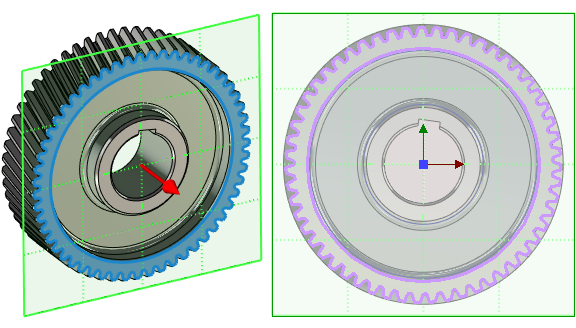
This command allows you to create a workplane relative to an object, the geometry of which allows the system to define the original plane and offset it by a specified value.
After selecting a 3D element, a new workplane appears in the 3D scene.
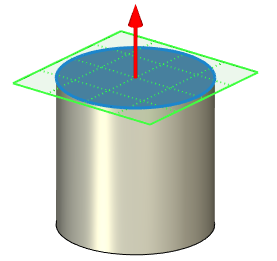
The initial position of the created workplane coincides with the position of the geometric plane defined by the parent 3D element. An exception is the case of creating a workplane relative to another work plane - then a small initial offset is set by default.
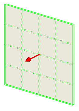
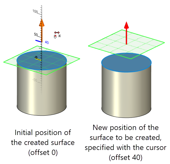
The final position of the created workplane can be defined using an offset value or using a point.
Defining position of offset workplane using offset value
Offset value can be typed into the Offset: input box in the command parameters window.
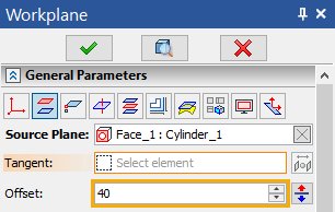
If necessary, you can change the direction of the workplane offset using the ![]() Reverse button.
Reverse button.
The offset value can also be set directly in the 3D scene using the manipulator in the same way as defining a translation along an axis of source LCS of transformations.
Defining position of offset workplane using point
In addition to the Offset: field there's also the Tangent: field in the command parameters window. Activation of this field enables filters for selecting points, faces and planes on the Filter toolbar.
Upon selecting a point, an offset workplane is created through selected point parallel to the source plane.
Upon selecting a plane, an offset workplane is created through selected workplane's LCS origin parallel to the source plane.
Upon selecting a face (doesn't matter if it's flat or not) two turquoise ball manipulators appear in 3D window. One manipulator represents the nearest point of a selected face in relation to the source plane. Another one represents the furthest point of a selected face in relation to the source plane. You can switch between these points using the ![]() Change Workplane Position button in the command parameters window or by clicking
Change Workplane Position button in the command parameters window or by clicking ![]() the desired manipulator in the 3D scene. An offset workplane is created through selected point parallel to the source plane.
the desired manipulator in the 3D scene. An offset workplane is created through selected point parallel to the source plane.
|
1 - Source Plane |
2 - "Tangent" face |
3 - Nearest point of "tangent" face |
4 - Furthest point of "tangent" face |
Additional Parameters
Additional Parameters tab of the offset workplane command parameters window contains the Project Selected Face to Workplane checkbox. If it's enabled a face selected as the Source Plane will be automatically projected onto created workplane. The rest of options on the Additional Parameters tab are common for all types of workplane. These option are described in the Workplane Parameters section.
Sequence of creation
1. Call the command.
2. Select source plane.
3. Select tangent (optional).
4. Set the offset (optional).
5. Set the workplane coordinate system (optional).
6. Customize additional parameters if necessary.
7. Confirm the creation of the workplane.