Workplane based on 2D Projection |
  
|
The command can be called in one of the following ways:
Icon |
Ribbon |
|
Support Geometry > Worksurfaces > Workplane based on 2D Projection |
Keyboard |
Textual Menu |
<3KSJ> |
|
Automenu of the |
|
<J> |
Based on 2D Projection |
This command allows you to create a workplane based on an existing 2D projection.
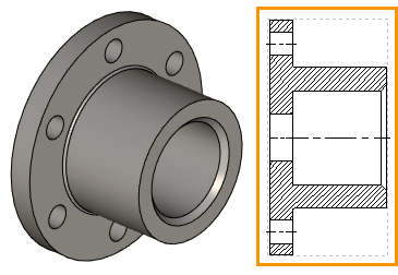
When creating a 2D projection, the projection plane is selected. When creating a workplane based on a 2D projection, its position in space is set by the projection plane of the selected surface (face, section, etc.)
The general scheme for creating work planes from a 2D projection is as follows.
First, the required 2D projection is created using the 2D Projection command. You can project the entire body, or a face, or other features.

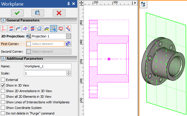
Then, in the command for creating workplanes, the created 2D projection is simply selected.

When using a 2D projection workplane, the elements (3D profiles, 3D paths, 3D nodes) defined on the basis of this workplane will be positioned in accordance with the position of the elements that were projected. It should be noted that the position of the workplane relative to the body will depend on how the 2D projection was set. If the projection direction was specified from a face, then the workplane will lie on this face. If the projection direction was specified by a section, then the workplane will be located in the plane of this section.
You can customize First and Second Corner of the border in the same way as described for Standard Workplane.
Additional Parameters are described in the corresponding section.
Sequence of creation
1. Create a 2D Projection from which the workplane will be created.
2. Call the command Workplane based on 2D Projection.
3. Select 2D Projection.
4. Set First and Second Corner of the border of the new workplane (optional).
5. Customize additional parameters if necessary.
6. Confirm the creation of the workplane.