Working with Workplanes using Rulers of 3D Window |
  
|
When working in the 3D window with the enabled rulers, there are additional capabilities for quick translation and copying of workplanes.
Visibility of rulers in the 3D window can be controlled with the help of Rulers command from the View ribbon tab, Window group.
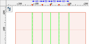
The rulers in the 3D window allow us to quickly estimate the sizes and distances in the 3D scene. Coordinates shown on the rulers constitute the coordinates on the imaginary plane parallel to the plane of the screen.
In case when the workplane is orthogonal to the plane of the current 3D view and positioned in it vertically or horizontally, the special marker on the ruler (![]() or
or ![]() ) will show the location of such a workplane.
) will show the location of such a workplane.
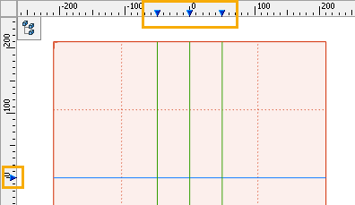
The marker of the workplane is closely linked with the workplane itself. When the cursor is moved to the sign of the marker, the color of the marker is changed to red. Moreover, the workplane itself is highlighted. Pressing ![]() on the sign of the marker invokes the context menu for the plane that corresponds to the given marker.
on the sign of the marker invokes the context menu for the plane that corresponds to the given marker.
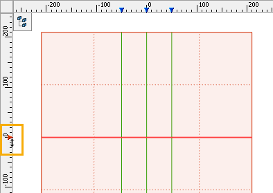
When the marker is selected using ![]() , the mode of moving/copying of the workplane is activated.
, the mode of moving/copying of the workplane is activated.
The translation of the selected plane is carried out if, after selection of the marker with the help of ![]() , the user moves the cursor without releasing the pressed mouse button. To fix the new location of the workplane, it is sufficient to release the mouse button. The exact value of the translation can be specified in the system toolbar or filter toolbar.
, the user moves the cursor without releasing the pressed mouse button. To fix the new location of the workplane, it is sufficient to release the mouse button. The exact value of the translation can be specified in the system toolbar or filter toolbar.
Creation of the new workplane – copying – takes place if, after selection of the marker with the help of ![]() , the pressed mouse button is released. Pressing
, the pressed mouse button is released. Pressing ![]() for the second time in this case will fix the location of already the new workplane – copy of the original plane.
for the second time in this case will fix the location of already the new workplane – copy of the original plane.
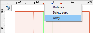
By using the <Shift> and <Ctrl> keys, it is possible to select several markers at once. Translation and copying in the case of multiple selection are carried out similarly to the selection of one marker. In the context menu the additional commands will be available:
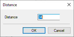
•Distance (available only upon selection of two markers) – this command is used for quick modification of the distance between the workplanes. When invoking the command, the Distance window appears in which it is necessary to indicate the required value of the distance. After pressing OK, the system will displace the corresponding workplanes in such a way that the distance between them becomes equal to the specified value;
•Equal Distance (available only upon selection of three or more markers) – this command displaces the planes, which are connected with the selected markers, in such a way that the distance between all adjacent planes becomes the same;
•Array – create an array of planes (only upon selection of two markers of planes).
In the context menu of the ruler of the 3D window two additional commands are available – Associative mode and Mark dimensions.
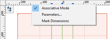
The Associative mode checkbox controls the mode of creation of workplanes with the help of tick marks on the rulers. When this checkbox is enabled, the new workplane's position is defined relative to the original workplane. When the checkbox is disabled, position of the new plane will be fixed in absolute coordinates without snapping to the original workplane.
The Mark dimensions checkbox controls the display of distances between the planes. When this checkbox is enabled, the distances of the selected workplanes between each other (if several of them were selected) and the distances to the first and last workplanes along the given axis are shown on the ruler as dimensions.
