Main Concepts of Workplane |
  
|
A workplane is a plane oriented in space with which 2D and 3D elements of a 3D model are associated. Depending on the type of workplane and the method of its construction, it is created in the 2D or 3D view window.
When creating a workplane in a 3D window, its position in space is determined either by the world coordinate system (standard workplanes), or by the elements of the 3D model. In this case, the workplane is assigned to a separate page of the drawing.
When created in the 2D view window, the workplane snaps to the elements of the 2D drawing and occupies an area on the current drawing page. That is, it is possible to arrange several workplanes on one drawing page.
Using the active workplane mode, you can create 2D elements belonging to the selected workplane in the 3D window.
Creating Workplanes in the 3D View Window
1. Standard workplanes correspond to the six standard views used in drawing. The standard workplanes are Front View, Back View, Top View, Bottom View, Left View, and Right View.
2. Workplanes based on solid elements (faces, vertices, edges) or 3D elements (3D nodes, 3D paths). Using the corresponding options of the Workplane command, you can define the position of the workplane in space using the above 3D elements.
There is a special way to create a workplane based on a body face. Point at the face with the mouse cursor (the selected face will be highlighted) and press ![]() . In the menu that appears, select
. In the menu that appears, select ![]() Draw on Face. The system will automatically create a workplane based on the corresponding face. When you select a face on which workplanes have already been created, the Draw on Workplane item will be available from the menu, containing a list of workplanes based on this face.
Draw on Face. The system will automatically create a workplane based on the corresponding face. When you select a face on which workplanes have already been created, the Draw on Workplane item will be available from the menu, containing a list of workplanes based on this face.
3. Workplanes created from another workplane.
By selecting an existing workplane, you can position the new workplane relative to the original, either by specifying an offset, or create a copy of it by specifying the source and target coordinate systems. Workplane offset is determined by snapping to 3D elements or in workplane parameters. Thus, by setting the offset, you can get a workplane parallel to the original one:
•with a given offset value;
•passing through a 3D point;
•tangent to the surface.
Creating Workplanes in the 2D View Window
1. Standard workplanes correspond to the six standard views used in drawing. The standard wor planes are Front View, Back View, Top View, Bottom View, Left View, and Right View.
2. Additional workplanes correspond to the arrow views used in drawing (view A-A, view E-E rotated). Additional workplanes can only be drawn when at least one workplane is specified. When constructing additional workplanes, only rectilinear views along the arrows are used, that is, without bends.
3. Workplanes based on 2D projection are defined based on the viewing direction in which the 2D projection was specified. This method is very intuitive, as it allows you to use the elements of the 3D model to define the position of the workplane. For example, you can create a 2D projection of any face of a 3D model and define the workplane through this projection. Then you can continue 2D construction using the face projection as the base. Thus, you can, for example, create a new 3D profile that will be used to create a new 3D object. This 3D object will lie directly on the face that was used in the 2D projection.
4.Workplanes based on 3D coordinate system are defined based on the position of one of the three main planes of the local coordinate system. This method is interesting in that it quite effectively allows you to position the workplane at any necessary point and at any angle.
Active workplane mode
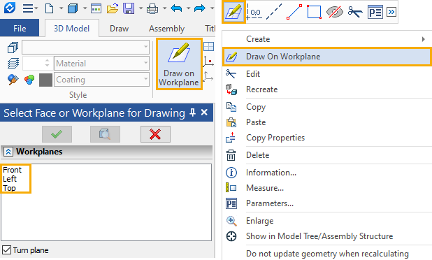
To switch to the active wor plane mode, call the context menu by pressing the right mouse button and select the Draw on Workplane item. Then select the necessary workplane from the list of all model workplanes. Or point with the mouse cursor to the workplane (it will be highlighted) and in the context menu also select the corresponding menu item.

The current workplane becomes active.
Working in the active workplane mode, you can use any commands for creating 2D elements (see Using Active Workplane).
Object selection
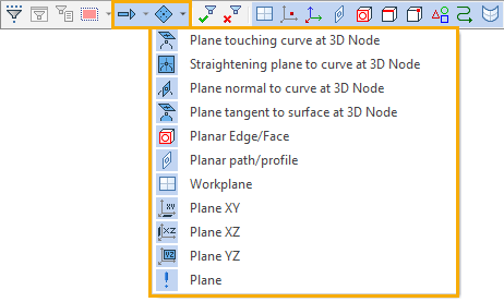
At the stage of selecting objects on the basis of which the workplane will be created, an advanced filter for selecting the type of geometry is available.

The rest of the filters define the set of element types allowed for selection (for example, face, 3D Profile, 3D Path, etc.).
![]()