Mates and Degrees of Freedom |
  
|
Mates and Degrees of Freedom |
|
In the process of designing solid assembly models in T-FLEX CAD, it is often necessary to specify mutual position of parts, which may not always be accomplished by the conventional technique of fixing by LCS adopted at T-FLEX CAD. This is due to the fact that changes in part positions may have to be reciprocal. A given part can simultaneously have multiple contacts with other movable parts. When using the approach based on LCS, recursive dependencies of references may occur in such cases (a part's dependency on itself). Such tasks may occur, for example, when building models of mechanical systems (mechanisms). To handle such tasks, mates are introduced which are the system elements that allow imposing various dependencies on the geometrical objects of two component operations (3D points, axes, curves, planes and surfaces).


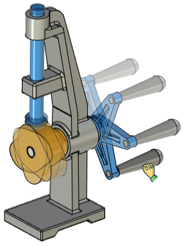
A model of a mechanism designed with the use of mates can be animated in the special command, where you move its parts by the mouse.
To fix a 3D fragment using LCS, you can specify additional conditions in the way of the permitted degrees of freedom. If such a 3D fragment is later attached via an LCS to another constrained element, then it will be included in calculations of the constrained mechanism. The method of positioning the selected parts by using mates is to be used as an auxiliary way of fixing together with the use of fixing by local coordinate systems. The use of mates requires additional computational resources for evaluating solutions. Therefore, we recommend using mates in the cases when other approaches to the described tasks are not suitable for some reasons.
What is a mate?
The "Mates" tool serves for mutual attachment of assembly model elements. It allows positioning those according to the specified geometrical conditions. These conditions define the mutual situation of the three-dimensional model objects (such as faces, edges, vertices, characteristic points, axes of surfaces of revolution, etc.) with respect to each other. The system automatically resolves the specified set of mates and situates the objects in the way satisfying the specified conditions. Mates allow precisely positioning the parts of the mechanism being designed with respect to each other. Those allow to impose certain properties in a mechanism's model and determine how its components move and turn with respect to other parts. Combinations of different mates can be used for more precise definition of the restrictions on an assembly element's position with respect to another element. Relations between pairs of components are associative. If one part is moved then another part will move along. For example, if a screw is tied to a hole, then relocation of the hole will cause the screw to follow along.
Mates are imposed on pairs of geometrical objects. Those either connect two components together or fix a body to its environment (with respect to a fixed object). A fixed object is an object with all its degrees of freedom restrained or a one whose position in the space remains still. It is recommended that at least one component be fixed in the space. This creates a "ground" for all other constrained parts and can prevent an unexpected dislocation of a mechanism's components.
Each mate appears as a model object having its place in the model structure. As a fully functional system object, a mate has a name, working properties and is displayed in the 3D model structure. The user can turn off some of the mates in order to temporarily exclude those from the general solution. This allows experimenting with various types of mates without redefining the mechanism interdependencies.
A 3D fragment applied to an assembly using local coordinate systems can also participate in a 3D model built on mates. To determine the behavior of a 3D fragment relative to the binding LCS, the allowed degrees of freedom are set in the fragment parameters. There are 6 degrees in total – 3 for movements and turns relative to the axes of the LCS. For each degree of freedom, an additional restriction of movement can be set in the form of a range of values.
You can also pre-set the degrees of freedom in the parameters of the source LCS, in the fragment file. When inserting a 3D fragment, conditions with degrees of freedom are copied into an instance of the 3D fragment and subsequently taken into account when calculating the complex of interfaces of the designed 3D assembly model.

If the target LCS was not specified when creating the 3D fragment, i.e. the fragment was bound "by default", then the mechanism of degrees of freedom will not be applicable to it.
When designing integral assemblies-mechanisms using degrees of freedom and mates, it is important to take into account the following point. A 3D fragment that is added to an assembly with an LCS binding can either be associated with some component of the assembly, or not. In the latter case, the behavior of the component when moving assembly components may not correspond to what is expected. For example, it will remain in place when the surrounding parts move, or, conversely, its movement will not cause the neighboring parts to move.
In order for a 3D fragment to be connected to another component, it is necessary that its target binding LCS be built on the geometric objects of this component. Otherwise, it will be tied to a stationary environment.
To create complex assemblies, the "Aggregates" mechanism is implemented in the system. This mechanism allows you to create interfaces first in the 3D fragment model, which will later be automatically taken into account when such a 3D fragment is working in the assembly.
To create a mate, use the Create command in the Assembly tab, the Mates group.
To dynamically view the movements of the assembled mechanism, use the Move command in the Assembly tab, the Mates group.
Optimal length of mated chains
When creating a mechanism, one part "clings" to the external environment, other parts are joined to each other by means of mates. Thus, a number of parts sequentially docked with each other can be represented as a chain of mates. If several other parts are connected to one part at the same time, then the chain of mates branches. When creating mechanisms, it is necessary to strive for the shortest possible chains. Shorter chains are solved faster and at the same time there is less error in calculations.
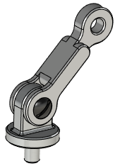
Consider the following typical example - it is necessary to create a model of a simple mechanism shown in the figure. The mechanism is a joint of a hinged type, combining three parts together - a support, a lever and an axis. The most rational way in this case would be to create two small chains of mates, rather than one long one.
The lever must be immediately tied to the support with the help of alignment mates and the coincidence of flat faces. The axis is also tied to any part, for example, to a support, using alignment and coincidence. It turns out two chains of mates: support-lever and support-axis. In this case, it would be irrational, for example, to tie an axis to the support, and to tie a lever to the axis, since a longer chain of "support-axis-lever" conjugations would result.
|
|
Mechanism example |
Mechanism parts |
|
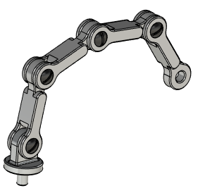
Complicating the mechanism (adding new mates) |
Of course, in such a simple example, there will be no noticeable deterioration in system performance, but in more complex cases, the difference becomes noticeable.
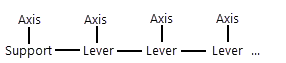

Rational chain Irrational chain
Topics in this section: