Mechanism Motion |
  
|
Calling the command:
Icon |
Ribbon |
|---|---|
|
3D Model > Additional > Move Mated Components Assembly (3D) > Mates > Move Sheet Metal (3D) > Additional > Move Mated Components |
Keyboard |
Textual Menu |
<3CM> |
Tools > Mate > Move Mated Components |
Upon calling the command, you are required to select the desired part of the mechanism for defining motion. Motion is defined by dragging the selected part by the mouse. In this way, the user stimulates an influence on the mechanism as if a force is applied to the selected point on the part in the direction of the mouse pointer in the screen plane. The part of the mechanism starts moving under the influence of the force. The motion is restricted by the specified mates with other parts and the outer environment. The selected part pulls another one, and so on, until the whole mechanism is involved in motion. In this simulation, masses and moments of inertia of the moved components are correctly accounted for.
Any translation and rotation parameters of mated (constrained) objects are recorded in the parameters of each mate operation. A special transformation type, namely, Mate Transformations, is created within the operation's parameters. All quantifiable parameters of this transformation are automatically calculated by the system.
Several important considerations shall be kept in mind when moving mated elements:
1. Exact numerical parameters cannot be specified for a translation.
2. Upon completing the translation command with ![]() , the parts cannot be brought back in the exact previous state. If urged, this can be done only by undoing the steps in the current session.
, the parts cannot be brought back in the exact previous state. If urged, this can be done only by undoing the steps in the current session.
3. When moving the model of the mechanism for which an assembly drawing was furnished, there is a danger of irreversible changes to the original drawing created by projecting. This could happen after refreshing the projection, due to the new positioning of the assembly parts and complications on the way of the exact rollback to the previous state of part positions.
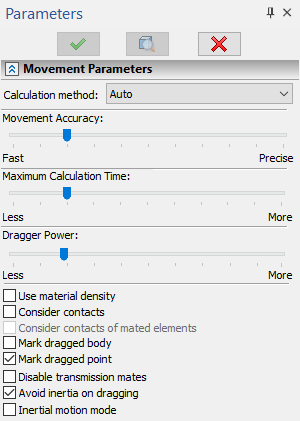
The setup of the motion modes is done in the parameters window.

The Calculation method sets one of two available calculation methods – Precise or Fast. The Precise method should be applied for systems containing up to several dozen hinges, the greater the order of the system, the slower the calculation will work. For systems involving hundreds of hinges, the calculation may work unsatisfactorily slowly. In such cases, a Fast method should be used, which copes equally well with both large and small systems. Auto mode allows the system to select the calculation method independently, depending on the complexity of the model.
The mode of the kinematic manipulator is used for moving parts in a mechanism. This results in smooth motion. It is a simulation of the effect of applying a force at the point at which the user pulls the part. The motion is generated by accounting for all specified restrictions. As the boundary of the solution domain is reached, the mechanism stops.
Movement Accuracy. This allows reducing the level of calculation precision for faster calculations and for maintaining the constraining conditions during a mechanism's motion.
Maximum Calculation Time. Sets the number of computational passes allowed to the system for reaching the required computational accuracy during the motion.
Dragger Power. This setting adjusts the degree of the mouse impact on the dragging point of the body. This setting controls the applied force and, therefore, how fast the dragged parts will move after the mouse.
Use material density. For more precise simulation of mechanism motion, a provision is made for accounting for the actual density when calculating mass properties of its parts. Otherwise, the density is assumed the same for all components.
Consider contacts. To improve accuracy of movement simulation there is an opportunity to consider contacts of bodies, except contacts between bodies mated to each other.
Consider contacts of mated elements. This checkbox can only be enabled, upon enabling the Consider contacts checkbox. Additionally enables considering contacts of bodies mated to each other. When considering contacts of mated elements, keep in mind, that there is a risk of generating unnecessary contacts, which may lead to undesirable consequences.
Mark dragged body. This is an auxiliary parameter for switching On/Off highlighting of the mechanism part being pulled at the user for inducing the motion.
Mark dragged point. This parameter turns on highlighting of the point which is pulled by the mouse pointer. The point is marked by a cross. This functionality can be used when the body highlight is off.
Disable transmission mates. This option allows disabling transmission mates. Such a capability is convenient for bringing transmission members to the starting mutual configuration (for example, the correct interlocking of wheel dents).
Avoid inertia of dragging. This parameter allows to switch on/off the consideration of the body inertia.
Inertial motion mode. This parameter allows to consider the inertia without its fading over time.
Record Animations for Moving Mated Elements
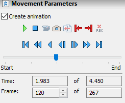
In the command to move the mated elements, there is a possibility to record an animation. This feature is activated by clicking the Create Animation option.
After clicking the option, the system goes into standby mode for moving the mated objects. While objects are moving, animation will be recorded. During the movement, frames and time are recorded. After the end of the move, the options for editing the record are activated.

![]() - Play
- Play
![]() - Stop
- Stop
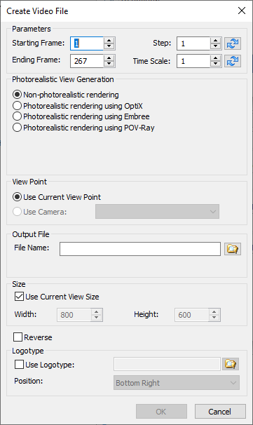
![]() - Create Video File. Opens the video creation settings window. The option is available after pressing the Stop button.
- Create Video File. Opens the video creation settings window. The option is available after pressing the Stop button.

The general parameters of this window are similar to the parameters of the Record Scenario window.
The exception is the presence of buttons ![]() for selecting the Optimal video duration without frames quantity changing and selecting the Optimal step of frames without video duration changing.
for selecting the Optimal video duration without frames quantity changing and selecting the Optimal step of frames without video duration changing.
It is possible to save the file in *.avi and *.wmv formats. After setting the settings, the system will start processing frames and after processing is completed, the video will be saved to the specified location on the disk.
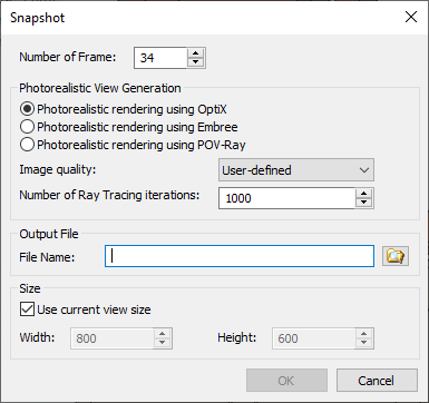
![]() - Take Snapshot. Opens the 3D window snapshot settings window.
- Take Snapshot. Opens the 3D window snapshot settings window.

In this window, there is an option to select the frame number for the snapshot and some of the parameters from the video creation window.
It is possible to save the file in *.png, *.bmp and *.jpeg formats. After setting the parameters, a photorealism generation window will open, in which the system will process the image properly and save it to the specified location on the disk.
![]() - Export Results. The option is active only after pressing the Stop button. After activating the option, a settings window opens, similar to the Export Scenario window. It is possible to export the script in the format *.wrl, *.x3d, *.pov, *.3d, *.pdf.
- Export Results. The option is active only after pressing the Stop button. After activating the option, a settings window opens, similar to the Export Scenario window. It is possible to export the script in the format *.wrl, *.x3d, *.pov, *.3d, *.pdf.
![]() - Trim Left. Allows you to trim frames to the current position.
- Trim Left. Allows you to trim frames to the current position.
![]() - Trim Right. Allows you to trim frames after the current position.
- Trim Right. Allows you to trim frames after the current position.
![]() - Delete Record.
- Delete Record.
![]() - To Start.
- To Start.
![]() - Rewind. Allows you to rewind the animation by holding down the left mouse button.
- Rewind. Allows you to rewind the animation by holding down the left mouse button.
![]() - Playback. Allows you to start the animation in the opposite direction.
- Playback. Allows you to start the animation in the opposite direction.
![]() - Previous Frame.
- Previous Frame.
![]() - Next Frame.
- Next Frame.
![]() - Fast Forward. Allows you to fast-forward the animation by holding down the left mouse button.
- Fast Forward. Allows you to fast-forward the animation by holding down the left mouse button.
![]() - To End.
- To End.
See Also: