Creating Mates |
  
|
To create a mate, use the command:
Icon |
Ribbon |
|---|---|
|
3D Model > Additional > Create Mate Assembly (3D) > Mates > New Sheet Metal (3D) > Additional > Create Mate |
Keyboard |
Textual Menu |
<3CT> |
Tools > Mate > Create Mate |
To create a new mate, complete the following steps:
1. Select the mate type.
2. Select the first object.
3. Select the second object.
4. Define parameters of the selected mate type (if necessary).
5. Confirm the selections.
Selecting mate type

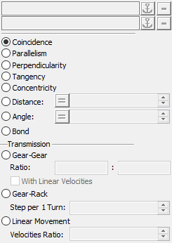
A mate type selection is done in the parameters window. To make a selection, set the radio switch into the desired state. For Distance and Angle mates, one can define a condition with respect to the specified value. Pressing the button before the numerical value cyclically switches its condition sign.
Selecting mate elements
The modes of selecting the first and second geometrical objects are engaged by the following options:
|
<F> |
Select first element |
|
<S> |
Select second element |
Upon selecting the first element, the system automatically turns on the option for selecting the second element. If it is necessary to return to defining the first element, turn on the respective mode manually.
For some mates, a number of options may be unavailable or temporarily inaccessible (see the tables of combinations above). Each option turns on a set of filters for selecting objects suitable for defining the required geometrical element.
Selected objects are highlighted. Also highlighted are the operations whose geometrical elements are selected. Simultaneously, the system offers a preliminary choice of solving the mate. According with this, the system moves the elements as to fulfill the mate conditions. If one or both elements already have mates with other bodies or fixed still to the environment, then the new solution is calculated by accounting for all earlier imposed restrictions.
![]()
When creating a mate, one of the two mate members can be fixed in the space. Fixing is done by pressing the button marked by an anchor image, in the parameters window.

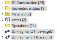
Upon fixing, the object becomes "frozen" in the 3D space in its current position. It will neither be affected by any new transformations nor by changes in parameters of existing translations. The "*" mark will appear before the name of the fixed operation in the model tree.
Repressing ![]() button cancels fixing of the mate component.
button cancels fixing of the mate component.
It is also possible to fix a body in space outside the command of mate creation. Use Fix Component from the context menu of any body if the current 3D assembly contains any mates or uses degrees of freedom for 3D fragments.
The command Fix Component is always available in the context menu of the fixed component. The icon corresponding to this command is pressed if a component is fixed. Applying this command will disable fixing in this case.
Selecting elements for defining transmission ratios
You need to specify numerical parameters (transmission ratios) when defining transmission mates. An additional capability is provided in the cases of Gear (angular speeds) or Worm (pinion-rack), which is using geometry of the mated elements to automatically determine the numerical transmission ratio. The options for defining the transmission ratio appear automatically in an additional section of the automenu when selecting the appropriate mate type.
The transmission ratio for the «gear» transmission is calculated as the ratio of the two selected elements' radii. The following options are used in the automenu:
|
<G> |
Select first element to define transmission ratio |
|
<D> |
Select second element to define transmission ratio |
|
<Z> |
Cancel transmission ratio selection |
In the case of the Worm mate, the transmission ratio is calculated based on the connecting thread parameters. The following options are used in the automenu:
|
<T> |
Select threaded face to define transmission ratio |
|
<R> |
Select edge or face to define transmission ratio |
|
<Z> |
Cancel transmission ratio selection |
Additional mate parameters

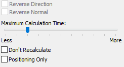
•Reverse Direction. This option rotates the second (or the remaining movable) component being connected by a 180 degrees or moves it into another solution domain. For the transmission mates, this parameter alters the direction of the second component motion.
•Reverse Normal. This option works only with the "distance"-type mate between two planes. In addition to the previous option, it allows changing the direction of counting the distance.
•Maximum Calculation Time is the parameter controlling the number of passes the system is allowed to use in search for the solution with the specified precision. This limitation is necessary to avoid too long system computations due to an accidental user error, that are possible when searching for solutions in complicated cases. This parameter is set by a slider.
If no solution was found after the current number of iterations, try to increase the allotment. On the other hand, it could be sufficient instead to manually move the components being connected toward the probable solution domain in the Move command.
•Don't Recalculate – this parameter suppresses mates calculation at the time of creation. This capability can be used in order to save time when working with large assemblies. This could be useful, for instance, when the user adds several mates one after another. To search for a solution, you will need to do full model recalculation. In this case, note that upon adding several complex mates or simply a too large number of mates, the system might not finally find the correct solution.
•Positioning Only – this parameter allows you to create a mate only for positioning two objects. When using this parameter, no mate will be created after the command is completed, but an additional non-associative transformation will appear in the model tree for objects.