Types of Mates |
  
|
Types of Mates |
|
When defining geometrical ties in the form of mates, you can use only the following geometrical terms: 3D point, axis, curve, plane, surface. In order to specify the geometrical data, the user selects topological elements of the model or construction elements. Use of 3D construction elements is possible under the condition that those are constructed based on an operation body. Otherwise, the second component will turn out to be bound to the still environment.
Upon fixing by construction elements, you lose the capability of dynamical articulation of the given connection in the constrained mechanism; therefore, if possible, prefer to use the model's topological elements (vertices, edges, faces, etc.)
When creating mates, make sure to understand the difference between the geometrical data used by mates and topological objects used for selection. For example, a flat face has boundaries, while the plane used in the mate is infinite. Therefore, the created geometrical relation based on a flat face will still be valid beyond the boundaries of this face.
If necessary, you can mate 3D fragments through 3D nodes derived in them and other construction elements.
Coincidence
This type of mate insures full coincidence of one geometrical object with another one. The number of remaining degrees of freedom depends on the geometrical type of the objects being joined. For example, aligning two points will create a spherical joint that blocks any translation while allowing any rotation. Aligning a point and a curve will allow elements to rotate, and also to slide along the curve. The following table shows the possible combinations of geometrical elements when using the coincidence:
A point can be aligned to any geometrical object. If two flat faces are selected, those will lie in one plane. Coincidence of an axis and a plane will insure the axis' placement on the plane of a flat face. The condition of coincidence between a point and a solid insures the point's placement being maintained on the solid's surface.
Upon selecting a circle and a conical surface, matching of the selected surface and the circle is realized in such a way that the plane of the circle is perpendicular to the axis of the cone.
Using the coincidence in combination with other types of mates allows imitating various mechanical connections. For example, coincidence of a pair of 3D points provides for a spherical joint.


Parallelism, perpendicularity
These types of mates represent a special case of the "angle" mate type. These insure mutual parallelism and perpendicularity of the selected geometrical objects. The following table presents the possible combinations of geometrical elements when creating parallelism or perpendicularity mates:
Tangency
Tangency insures a constant physical contact between two geometrical objects. Depending on the geometry type of the interacting objects, a contact may be occurring in one point (example: a plane and a sphere) or along a line (a plane and a cylinder). This type of mate can be set between two planes, a plane and a surface, two surfaces.
Tangency between an arbitrary body and a surface works only for a spherical surface.
Tangency between two cones works only if both cones are selected as ![]() geometric surfaces (see Filters of 3D Geometry Type).
geometric surfaces (see Filters of 3D Geometry Type).
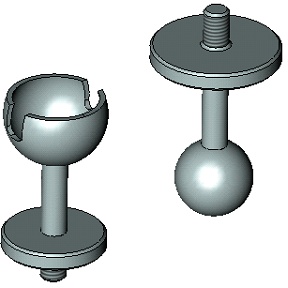
Sometimes, there are several possible solutions to connecting the selected objects. For example, if a plane and a sphere are selected, then the solution yields two tangency points. In the case of a non-unique solution, the system makes a decision automatically. Normally, the nearest point to the current location of the mechanism is accepted as the solution. To transit to another solution domain attainable by the moving mechanism, use the "dragging" motion mode (see below).

1. First solution for tangency
2. Spherical surface (first constraint member)
3. Cam surface (second constraint member)
4. Second solution for tangency
In the case of a non-unique solution, it is recommended to bring the components being constrained into the area of the desired result before creating the mate. Parts of a constrained mechanism can be moved within the command Move Mated Components. The components that were not yet subjected to mates, can be moved by using the command Transformation.
Concentricity
"Concentricity" is a special case of the "coincidence" mate type. It insures coincidence of two axes. This type of mate is a most commonly used one. Normally, this mate type is engaged in combination with other types. For example, to snap a part with an axis to a hole, coincidence (of flat end faces) is used quite often in combination with concentricity. To define concentricity, one can select model elements suitable for defining an axis (surfaces of revolution, elliptical edges, straight edges, etc.).
The diagrams show constraining parts of a schematic hydraulic cylinder by concentricity. Other parts of the simple mechanism arc connected by local coordinate systems. For viewing convenience, some parts of the mechanism are sectioned along the axis.

1. Attachment by LCS - Allowed is the rotation about X-axis
2. Attachment by LCS - Allowed is the rotation about X-axis
3. Attachment by LCS - Allowed are rotations about and translation along the X-axis
4. Concentricity constraint has been created
Distance
The "Distance" mate defines a relation between two objects by fulfilling the condition of maintaining a specified distance between two geometrical objects. One can specify the conditions of types "no greater than", "no less than" or "equal" to the specified value.
The following table presents the possible combinations of geometrical elements when creating the "distance" mate:
This type of mate can be used, for example, for defining an object's shift or for restricting mutual penetration of faces. To define a restriction on mutual penetration of faces of different parts, you just need to specify the distance condition "no less than" zero. This can be used for mechanisms whose operation relies on physical contact (collision) of its parts.
Continuing with the hydraulic cylinder example, let us show how to use the "distance" mate. The mechanism created at the previous step will operate incorrectly in certain motions, because some parts of the hydraulic cylinder may penetrate each other. This problem is resolved by the "distance" mate. One can specify the condition that the distance between the respective faces of the piston and the cylinder must be greater than or equal to zero. When mates are dragged kinematically, this will yield the correct representation of the mechanism's behavior.

1. Constraints are defined as the distance condition between faces being no less than zero
2. Constraints enabled
3. No constraints
Angle
This mate defines angular distance between two geometrical objects. The turn angle can be used for rotating a component referencing the desired position. Just as in the "distance" case, this mate type supports use of conditions. When defining such connection, normally there are two or more solutions.
Bond
This type allows you to create a mate of two objects so that they move as one.
«Gear-Gear» Transmission
This type of mate serves for creating conditions for the interaction of two bodies spinning about their respective axes. The conditions are specified as a transmission ratio between two spinning objects, that is, the number of revolutions made by one of the components while turning the other one. Upon introducing such a mate, a two-sided relation is formed. This type of mate is convenient for monitoring mechanisms that incorporate dented wheel or belt drives.
Remember that this type of transmission relation, just like any other transmission mate, merely tells the system the mutual ratio of angular (in this context) velocities. Also note that each component must be fully fixed in its place by the time of creating a transmission mate and be assigned all required degrees of freedom and constraints.
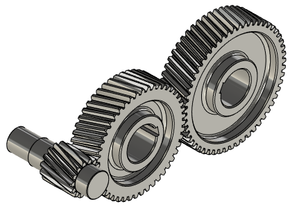
To create such a mate, select two axes of revolution and specify the transmission ratio. In this case, the shape of the dented wheel is not significant for the system, as the wheel dents can be created for «cosmetic» purpose only. The law of the mechanism's movement will be defined solely by the mate conditions.
«Gear-Rack» Transmission
This type of mate serves for creating the conditions for two interacting bodies, in which one component spins, while the other one moves about one or multiple axes. This type of mate allows modeling, for instance, a nut being picked up by a screw, a transmission link of the type «pinion-rack», etc. The mate conditions are defined as the amount of the distance traveled by the movable component along the specified axis while the other component makes one full turn. A two-directional relation results from creating this kind of mate.
To create a mate, you need to define the axis for each of the two components and specify the distance in the model units that one component would travel while the other component rotates by 360 degrees. The first one defines the «pinion» axis, the second one - the «rack» axis.
«Linear Movement» Transmission
If there are two objects in the model moving in their respective axial directions, then you can specify a ratio using the mate being described, that would characterize the mutual displacement of the two objects. With such a relation established, the travel distance of the second component will be calculated by multiplying the first component's travel by the specified ratio. The relation can work in the reverse direction as well (from the second component to the first one); in this case, the system will use the ratio which is the reciprocal of the specified one. This type of mate helps modeling the mechanisms representing systems of pulleys, hydraulic mechanisms, etc.

To create a mate, you need to define the axes for each of the two components, and enter the value of the velocities ratio of the moving components in the provided input box.