Adaptive Elements of Non-Adaptive 3D Fragment |
  
|
The system supports defining the list of external parameters and their instantiating values for both inserting new fragments and editing existing fragments in an assembly. To add an additional parameter, call the command for editing a 3D fragment. In the Geometric Parameters section of the parameters window, press the button and select the 3D fragment model's element to become an external parameter. The next step will be either instantiating its value or adding more parameters to the list. The difference of this approach from the steps described in the Create Adaptive 3D Fragment section is that such changes in the list are remembered only in the current assembly. When inserting this 3D fragment into another assembly model, the elements added to the list will not be available. Therefore, any 3D fragment of an assembly model can be converted to an adaptive 3D fragment, and the predefined list of geometrical parameters of an existing adaptive 3D fragment can be extended.
Example:
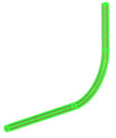
Create a Route in a new assembly document and insert a fragment that has similar geometry, for example, a pipe created along a 3D path.
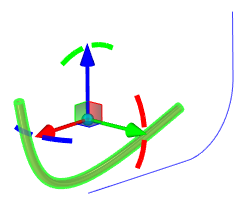
In the Geometric Parameters tab, click the ![]() button. A window for selecting the geometry of the source fragment will open on the left. Select the 3D path of the fragment.
button. A window for selecting the geometry of the source fragment will open on the left. Select the 3D path of the fragment.
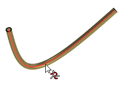
The selected 3D path appears in the Parameter field on the Geometric Parameters tab.
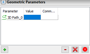
Next, in the assembly document, select the Route. The selected Route will appear in the Value field on the Geometric Parameters tab.
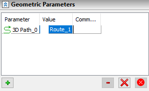
As a result, the pipe geometry will take the shape specified by the Route.
