Document Converter |
  
|
Calling the command:
Icon |
Ribbon |
|---|---|
|
File > Document Converter Get Started > Files > Document Converter |
Keyboard |
Textual Menu |
<AC> |
File > Document Converter |
This command regenerates and re-saves assemblies with fragments and/or files containing individual parts. The need to perform this procedure arises when switching to a new version of the system, because this changes the current GRB file format. When you open a file created in one of the previous versions of the system, a full regeneration is automatically started to write data in the format of the new version, so the time for opening old files increases. However, after saving the regenerated file, reopening is much faster (in this case, there is no regeneration anymore). To increase the speed of the system with the assembly model (drawing), it is necessary to regenerate and save all the fragments included in it. Resave should be done from the "bottom up" the assembly structure. The document converter of previous versions allows you to perform this procedure automatically, i.e. defines the entire hierarchy of the fragments included in the assembly and performs their regeneration and saving in the necessary sequence (first, fragments of the lower level are opened, regenerated and saved, then the previous, etc., up to the assembly file). In the process of converting files, a report is generated in which the results of the work (warnings, informational messages, errors) are recorded. The original files can be saved as backups.
After calling this command, the converter window will appear on the screen. It is divided into 3 areas:
•Area with the list of files (upper left);
•Area with the service information and buttons (upper right);
•Area of diagnostics and display of messages about the progress on the conversion process (the lower part of window).
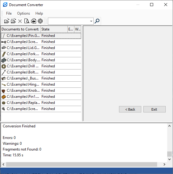
The list of files selected for conversion is shown in the upper left field of the converter dialog. By default, the list of files is empty.
If some documents were open in T-FLEX CAD at the time of calling the command, the system will prompt you for closing them (this is required for successful converter operation) and will automatically add them to the list of files to be converted. If necessary, the user can remove some files from the list and/or add other T-FLEX CAD documents to the list.
To add files to the list, the Add Files, Add Folder and Add from T-FLEX DOCs (if the T-FLEX DOCs integration mode is enabled) buttons found on the toolbar of the converter can be used. These commands can be also called from the textual menu.
The first button allows adding separate documents to the list, while the second one – all T-FLEX CAD documents in the selected folder. If the selected folder has subfolders, the system will ask you, whether to add those to the list.
To delete a file from the list, select it in the list and press the Delete Files from List button or the button <Del>. To complete creation of the file list for conversion, press the Next button .
In the progress of conversion, the system may automatically decide to add to the conversion list the necessary fragment files of the assemblies being converted, upon analyzing the structure of the model to be converted. This behavior can be controlled by a conversion parameter (see the Customization of Converter section).
Performing Conversion
After forming the list of converted files, press the button Next in the right part of the converter window. After pressing this button, the contents of the upper left area of the converter window will be modified. The list of the converted files will be replaced by the list of the T-FLEX CAD libraries. At this stage, a user has to indicate the elements of which libraries should be subject to transformation, if they are found in the structure of the converted documents. The libraries the elements of which can be converted are marked with a “tick” in the list of the libraries (to mark it, point with the cursor at the symbol ![]() next to the name of the library and press
next to the name of the library and press ![]() ).
).
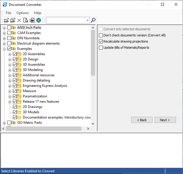
Parameters shown at this step in the right part of the converter window duplicate parameters in the conversion options dialog (see the Customization of Converter section).
After specifying libraries the elements of which can be modified upon conversion, press the button Next again to proceed to the next step.
To return to the step of selecting documents (for example, if you need to modify the list of selected files), use the graphic button Back.
At the next step, the structure of relations of converted files will be shown in the upper left area of the converter window. If necessary, additional files are added to the list, that correspond to the fragments of the assemblies being converted.
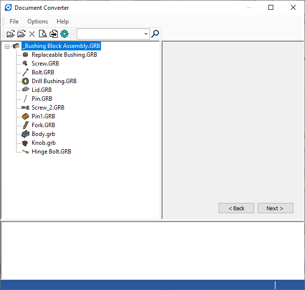
To start regeneration of selected files, press the button Next again.
The step of library selection and viewing the document connections structure can be skipped, if for proceeding to the next step of the conversion process, a user does not press the button Next, but rather calls the Preview command and Convert command found on the toolbar or in the textual menu of the converter. In this case, for the library elements the default settings will be used (by default, conversion is allowed only for user-defined libraries; standard libraries supplied with the system are not converted).
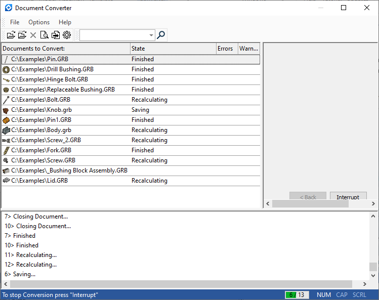
In the process of regeneration of selected files, the information on the progress and results of the converter actions will be displayed in the lower part of the converter window, whereas in the upper left area a user can view again the list of the files being converted in which the current state of working with each file is shown. A progress bar of files being processed is displayed in the lower right corner.
When converting documents containing a specification of the old type (using a database in an external file), a message will be displayed about converting the specification to a new format and breaking the link with the database file.
After completing the file transformation, in the lower part of the converter window, the message about the process completion and indicating the number of occurred errors will be displayed.
To close the application press the graphic button Exit.
Customization of Converter
The conversion process settings dialog is called from the text menu Options > Options….
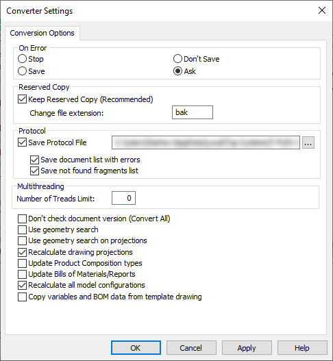
The group of parameters "When Error Occurred" defines the system response on the occurrence of errors during regeneration or saving of the documents:
Stop – stop the conversion;
Save – saved the document despite the errors;
Do Not Save – do not save a document if errors occurred during its regeneration;
Ask – display a dialog box with the error message and ask the user about further actions.
The group of parameters Backup Copy allows turning on the mode of creating backup copies of all the files with the specified extension.
The group of parameters Log is provided for controlling the information displayed in the lower part of the converter window and in the protocol file.
The flag Save Log allows saving the information about the conversion process in the protocol file. The name and the path of the protocol file can be specified to the right of this flag. If this flag is disabled, the protocol file is not saved.
The parameters Output List of Documents with Errors and Output List of not found Fragments control the output of certain information into the log.
The group Multithreading has only one parameter Number of Treads Limit:. It allows a user to limit the maximum number of simultaneously started processes upon the conversion.
Upon conversion, the T-FLEX starts several processes in which simultaneous regeneration of not depending on each other files takes place (if they do not have relationship parent/child in the assembly). While doing it, by default, to achieve the maximum effectiveness, the number of started processes is equal to the number of processors on the computer (this allows engaging all resources of the computer). This parameter allows put a limit on the number of processes and the computer resources used by the processes.
The parameter Convert Selected Documents Only (ignore children) is provided for selecting the mode of assembly conversion. If set, only the selected files will be converted. The fragment documents that belong to the current assembly, yet are not specified in the file list, will not be converted.
Don't Check Documents Versions (Resave All). If not set, the documents in the up to date version of T-FLEX CAD format will not be converted (except the assemblies, whose fragments were converted). If set, all files will be converted, regardless of the format.
The following group of parameters is used only when converting documents containing 3D models:
Use geometry search. With this parameter turned on, if errors occur during the model element regeneration (for example, an error regenerating a 3D node created at a body vertex, or an error regenerating an edge or face blend), the geometry search procedure is launched, that allows restoring the lost geometry references.
Use of the mode Use geometry search is strongly recommended with the files of the versions earlier then 7.2. However, in some rare cases, use of this procedure may result in establishing incorrect references within the model.
Use geometry search on projections. This parameter turns on handling of the regeneration errors that occur in the elements based on 2D projection lines. The error handling procedure restores references of these elements.
Regenerate drawing projections. With this parameter set, all 2D projections are regenerated regardless of the projection parameter setting "Update". Regeneration of projections and sections of complex models may take considerable time, therefore it should be unchecked if desired.
Update BOMs. This parameter controls recalculation of all BOMs of the document. It is disabled by default.
Recalculate All Model Configurations. If this parameter is set, then the configurations present in the document being converted are resaved when converted.
Copy variables and BOM data from template drawing. If this parameter is set, hidden system variables for working with data for the specification (based on document prototypes) are automatically created in files converted from formats of versions 7.2 and below.
Variables are copied only if there is no variable in the converted document that matches the name of the variables in the prototype. The data for the BOM is copied if there is no data for the BOM in the document and the variables were copied. For drawings, a 2D drawing prototype is used, for 3D models - a 3D model prototype.
Recommended order of steps when converting models from older versions of T-FLEX CAD
1. Set aside backup copies of documents.
2. Make sure that the complete regeneration of the model in the previous version of T-FLEX CAD passes without error messages, and the assembly opening without messages about missing fragment files.
3. Run the converter with the default values (the modes Recalculate all model configurations, Recalculate drawing projections are enabled).
4. For models with complex projections (sections, sections) - the Use geometric search on projections and Recalculate drawing projections checkboxes make sense to use when the transformation with disabled modes did not lead to the desired result (especially for the Use geometry search on projections mode). Enabling these modes can lead to a significant increase in conversion time.
5. In case of problems with the search for design elements in the drawing, restart the converter with the added flag Use geometry search in projections.
6. If on very large assembly models the system fails to recalculate projections due to lack of RAM, then conversion is possible with the Recalculate drawing projections flag turned off.
Enabling the Use geometry search mode is especially recommended for files created in versions earlier than 7.2. However, its inclusion in a number of rare cases can lead to the construction of incorrect links in the model.