Additional Parameters of Loft |
  
|
Trim Option
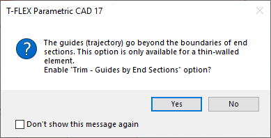
If guides (trajectory) are selected that are longer than the boundaries of the sections, the system will offer to enable the Trim - Guides by End Sections option, which will allow using only that part of the guide that is located between the first and last sections.

Without Trim |
With Trim - Guides by End Sections |
|
|
1. Guide 2. Open section |
|
Similarly, you can trim sections using the Trim - Sections by End Guides guides option. To trim sections, you need at least 2 guides or 1 guide and a trajectory, with the Use trajectory as guide option enabled. Section trimming is possible only for open sections.
Without Trim |
With Trim - Sections by End Guides |
|
|
1. Guide 2. Open section |
|
If necessary, you can trim both guides and sections at the same time as described above. To do this, use the Trim - Sections and Guides option.
Without Trim |
With Trim - Sections and Guides |
|
|
1. Guide 2. Open section |
|
These options are created to work with solids and surface bodies. If the Periodic option is enabled, trimming will not work.
Periodic Option
Used to create closed bodies or surfaces. When this parameter is set, the last section is closed with the first. This parameter can be set if no points are specified as the first and last section, and also if special conditions are not specified for the first and last sections.
Non-Periodic Body |
|
1. First section 2. Second section 3. Third section |
Periodic Body |
|
When using guides and setting the Periodic option, the guides must be closed.
|
|
|
1. Start match 2. Guide 3. First section (3D Path) |
4. Second section (3D Path) 5. Third section (3D Path) |
|
Linear Option
If the flag is set, then linear bodies are created, if it is cleared, then smooth bodies are created. A linear body is the result of connecting a pair of sections by generatrices-straight lines.
Smooth Body |
Linear Body |
|
|
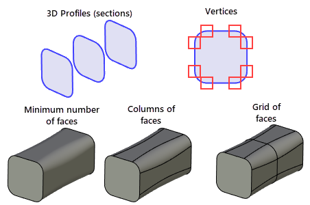
This parameter determines how the new faces should split the resulting body. There are 3 options - Minimum, Columns, Grid.
The columns are produced by dividing the body along the sections direction at each profile vertex.
The grid is produced by dividing the body into columns and then dividing along the body according to the position of the sections.

Derived Quantities Parameter
When using boundary conditions, where the value of the derivative is specified through a scale factor, the system first determines the “Default” value of the derivative on the selected section. The scale factor value is then multiplied by the calculated value of the “Default” derivative. With these options, you can choose different behavior for the computed value of the “Default” derivative. It is recommended to use the Smooth Variation along Body option.
Optimization Parameters
The Tolerance parameter specifies the maximum allowed gap between profiles and guides. Thus, for example, setting rough (large) tolerance in some cases allows handling a situation when the sections and guides do not intersect, but pass near each other. The tolerance defines the distance between them that the system can ignore by assuming that the guides and sections do intersect. Besides, the tolerance affects the minimum size of a profile edge that is defined as ten times the tolerance value. Consequently, the same limit is used as the minimum distance between two distinct match points on a profile, as well as between start points of boundary conditions defining vectors. The lower tolerance limit is 10-8. However, keep in mind that a too small tolerance may slow down the system operation. The system default tolerance is 10-5.
The Simplify Geometry flag is used for simplifying the geometry and topology of the resulting surface. With this flag on, analytical surfaces are created instead of splines whenever possible, such as a torus, a cylinder, a sphere and a plane.
Using the created loft in a Boolean
To create a Boolean operation, do the following:
1. Turn on the Boolean creation mode by the automenu option
|
<Ctrl+B> |
Select original body for Boolean operation |
A Boolean is created when the icon is pushed.
2. Select the type of the operation from the pull-down list under the above option:
|
<Ctrl+'+'> |
Addition |
|
<Ctrl+'-'> |
Subtraction |
|
<Ctrl+’*’> |
Intersection |
|
<Ctrl+’I’> |
Smart mode |
Operating principles of the Smart mode
•If the body being created and the existed selected body have intersection of volumes - the type of Boolean operations: subtraction.
•If the body being created lies entirely within the selected body - the type of Boolean operations: subtraction.
•If the body being created touches and selected body touch each other - the type of Boolean operations: addition.
•If conditions set out above are not met, or a selected body lies inside the created, or error occurred determining the type of penetration, then, Boolean type is not defined - the Boolean operation will not be created.
3. Select the target body for the Boolean (optional in some cases), using the automenu option
|
<Ctrl+T> |
Select Target Body for Boolean |
If only one body exists in the scene, it is selected automatically. The new body created by the extrusion operation becomes the tool body of the Boolean.
Upon confirming operation creation, first the body is created by the loft operation, and then the specified type Boolean is performed.