Boundary Conditions of Loft |
  
|
Boundary Conditions of Loft |
|
Different boundary conditions can be specified for different sections/guides/match points. They are set in order to provide a more accurate surface, including the formation of smooth transitions. As it was said in main concepts, there are 4 boundary conditions in total - By Normal, By Tangent, By Geometry and By Vectors. For ordinary (planar/non-planar) sections, all boundary conditions are available.
For a section-point, as well as for match points, only one boundary condition is available - By Vectors, and for guides only two boundary conditions are available - By Geometry and By Vectors.
Basically, the principle of operation of boundary conditions for guides and match points does not differ from the principle of operation of boundary conditions for sections, therefore, below will be a description of creating boundary conditions for sections. Some of the distinguishing features of the boundary conditions for guides and match points are shown at the bottom of the page.
Boundary condition is not selected
If the boundary condition is not selected, then the surface is created along the vertices of the sections without additional smooth transitions.
|
1. First section 2. Second section |
Boundary condition "By Normal"
If the boundary condition By Normal is selected, then the surface is created taking into account the normal vector of the selected section. A prerequisite is the presence of a normal for the selected section.
Without boundary condition |
Boundary condition "By Normal" for both sections |
|
|
1. Section normals |
|
The sequence of actions for defining the boundary condition By Normal is as follows:
1. Select the required section in the general list of sections.
2. Select the boundary condition By Normal.
3. Select the type of length of the normal vector, and set its value.
4. Reverse the direction of the normal vector (optional).
Items 3 and 4 are described below in the Additional parameters of boundary conditions section.
Boundary condition "By Tangent"
If the boundary condition By Tangent is selected, then the surface is created either taking into account the vectors directed along the tangent, or taking into account the normal.
Without boundary condition |
Boundary condition "By Tangent", type |
|
|
1. Vectors directed along the tangent 2. Section normals |
|
The sequence of actions for defining the boundary condition By Tangent is as follows:
1. Select the required section in the general list of sections.
2. Select the boundary condition By Tangent.
3. Select the type of boundary condition - By Vectors or By Normal.
By Vectors type allows you to create a surface using planar or non-planar sections, taking into account vectors directed along the tangent.
Top View |
Boundary condition "By Tangent", type "By Vectors" for first section in an arbitrary view |
|
|
1. First section 2. Second section 3. Vectors directed along the tangent |
|
By Normal type allows you to create a surface only by planar sections, taking into account the normal. The direction depends on the position of the next section.
Top View |
Boundary condition "By Tangent", type "By Normal" for first section in an arbitrary view |
|
|
1. First section 2. Second section 3. Normal |
|
A prerequisite is the presence of a normal for the selected section.
To obtain the "classic" boundary condition By Tangent, it is recommended to use the type By Vectors.
4. Select the type of length of the normal vector, and set its value.
5. Reverse the direction of the vector (optional).
Items 4 and 5 are described below in the Additional parameters of boundary conditions section.
Boundary condition "By Geometry"
If the boundary condition By geometry is selected, then the surface is created taking into account the tangency to the selected face or a set of faces. If there are multiple faces adjacent to a framing element, it is not necessary to select all of them.
Without boundary condition |
Boundary condition |
|
|
1. Tangency vectors |
|
You should remember about the need to comply with some restrictions:
•The processed element (section, guide or their segment) must lie entirely on the selected face;
•The selected face must end on the element being processed;
•You cannot set a face for a framing element (element segment) in one direction if it intersects with a framing element in the other direction. This means that if guides are specified in the operation, then this boundary condition is not applicable for the entire section. In some exceptional cases, when using open sections, the system allows you to use this boundary condition in the presence of one guide.
The sequence of actions for defining the boundary condition By Geometry is as follows:
1. Select the required section in the general list of sections.
2. Select the boundary condition By Tangent.
3. Select a face or set of faces that will define the boundary condition in the section.
The section to be processed must coincide with the face of the body. The contact of the future surface will be provided to the adjacent faces of the body.
4. Select continuity type G1 or G2 (optional).
G1 connects profiled curved surfaces with tangential continuity to boundary surfaces. G2 connects profiled curved surfaces with curvature continuity to the boundary conditions.
G1 for both sections |
G2 for both sections |
|
|
1. Face that "touches" the top section 2. Face that "touches" the bottom section |
|
5. Activate the account of the scale factor and set its value (optional).
6. Reverse the direction of the vector (optional).
Items 5 and 6 are described below in the Additional parameters of boundary conditions section.
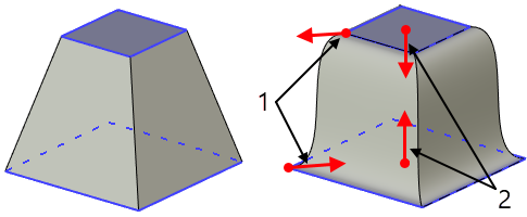
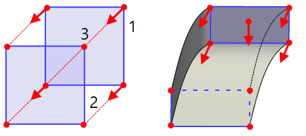
Boundary condition "By Vectors" for planar and non-planar sections
If the boundary condition By Vectors is selected for a planar or non-planar section, then the surface is created taking into account the tangent vectors emerging from the selected points. You can select vertices, 3D nodes, or points as points anywhere on any edge of the section. A prerequisite is that the point belongs to the selected section. You can select an unlimited number of points from which tangent vectors will be created.
Without boundary condition |
Boundary condition |
|
|
1. First open section 2. Second open section 3. Guide |
|
The sequence of actions for defining the boundary condition By Vectors for planar and non-planar sections is as follows:
1. Select the required planar/non-planar section in the general list of sections.
2. Select the boundary condition By Vectors.
3. Select the first point of vector 1.
If an arbitrary point on the edge is selected as the first point of the vector, an additional dialog will appear in the operation parameters, where it will be possible to set the coordinates type of point, the base point and set the position of the point on the edge.

The position of a point on an edge relative to the origin is determined by the U coordinate.The U coordinate implies two types of values:
•By Offset. For this type, the units of length must be considered.
•Parametric. For this type, the value has a unitless form (fraction of the length) from 0 to 1.
The system also provides the ability to select the base point of the U coordinate:
•Start. In this case, the base point is the starting point of the edge;
•Middle. In this case, the base point is the middle point of the edge;
•End. In this case, the base point is the end point of the edge;
The position of a point on an edge is set either manually using the Position field, or using a manipulator on a selected edge.

If a 3D node or a vertex is selected as a point, then an additional dialog on point location does not appear.
4. Select the type of length of the vector, and set its value.
5. Select the type of vector definition, and set the appropriate parameters.
6. Reverse the direction of the vector (optional).
7. Activate the option For All Vertices (optional).
This option is used when it is necessary to set the current parameters of the selected vector for all free vertices. Free vertices are all vertices of the section, except for the vertices of intersection with the guides and except for the correspondence points, which have a boundary condition. When this option is activated, it will no longer be possible to select additional vectors.
Items 4 and 6 are described below in the Additional parameters of boundary conditions section.
Item 5 is described below in the Vector defining types section.
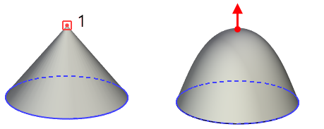
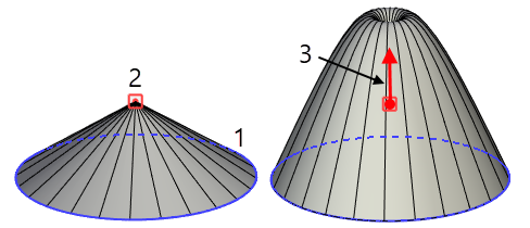
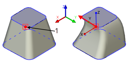
Boundary condition "By Vectors" for section-points
If the boundary condition By Vectors for the section-point is selected, then the surface is created taking into account the tangent vector outgoing from the section-point.
Without boundary condition |
Boundary condition |
|
|
1. Section-point |
|
The sequence of actions for defining the boundary condition By Vectors for section-points is as follows:
1. Select the required section-point in the general list of sections.
2. Select the boundary condition By Vectors.
3. Select the type of condition for specifying the vector.
There are 2 types of vector specification conditions - By Normal and By Tangent.
By Normal provides smooth ending for the created surface, limiting it to a tangent plane with a specified normal at the section-point. The normal is determined by the type of its vector definition - by spherical or cartesian coordinates, by two points, or by direction.
|
1. Planar section 2. Section-point 3. Normal |
By Tangent produces a more general ending which may or may not be smooth, constraining the surface by limiting it with a vector of derivatives in a section-point. The vector is determined by the type of its definition - by spherical or cartesian coordinates, by two points, or by direction.
|
1. Planar section 2. Section-point 3. Vector with a given scale factor |
4. Select the type of length of the vector, and set its value.
5. Select the type of vector definition, and set the appropriate parameters.
6. Reverse the direction of the vector (optional).
Items 4 and 6 are described below in the Additional parameters of boundary conditions section.
Item 5 is described below in the Vector defining types section.
Vector defining types
For boundary condition By Vectors, it is possible to specify 4 types of specifying the direction of the vector - In Cartesian Coordinates, In Spherical Coordinates, By Two Points, By Direction.
If the type Cartesian Coordinates is selected, then it becomes possible to specify the coordinates X, Y, Z, and also select the LCS for the vector. If LCS is not selected, then the vector is created in the global coordinate system.
Without boundary condition |
Vector specified in Cartesian coordinates |
|
|
1. First Point |
|
If the Spherical Coordinates type is selected, then it becomes possible to set the polar and azimuthal angles, as well as to select the LCS for the vector. If the LCS is not selected, then the vector is created in the global coordinate system.
Without boundary condition |
Vector specified in Spherical coordinates |
|
|
1. First Point 2. Polar angle 35° 3. Azimuthal angle 25° |
|
If the By Two Points type is selected, then it becomes possible to specify the second (end) point of the vector, which determines its direction. Any point in the 3D scene can be selected as the second point. The starting point belonging to the selected section is used as the first point.
Without boundary condition |
Vector specified by two points |
|
|
1. First Point 2. Second Point |
|
If the By Direction type is selected, it becomes possible to select an object, the direction of which must coincide with the direction of the vector. As such an object, you can select any object in the 3D scene that has a direction. The direction is taken from the object itself, along the normal to the object's plane, or along the axis of rotation of the surface of rotation.
Without boundary condition |
Vector specified along the edge of another body |
|
|
1. First Point |
|
Designation of vectors in a 3D scene
For the boundary condition By Vectors, vectors outgoing from the selected points are marked as follows - green arrows for sections, yellow for guides, blue for matches.
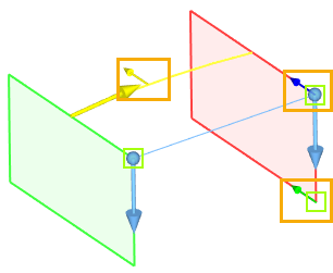
The size of such arrows is 2 times smaller than the size of the arrows indicating the contour bypass direction. Clicking on such a manipulator activates it and the system will go to editing the vector for the corresponding element.
Additional parameters of boundary conditions
For each boundary condition, you can set a certain type of length of its vector or normal, or change the direction of the vector.
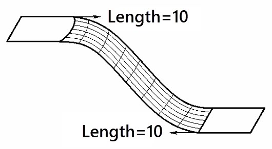
There are 2 types of vector length - Length and Scale Factor. These 2 types determine the degree of influence of the boundary condition on the curvature of the future surface. If the first type is selected, the user manually sets the length of the direction vector.
The value is set in absolute model units, so the required number depends on the model size. With large model sizes, you need to set large numerical values to achieve the same effect.


If the second type is selected, the user manually sets the scale factor by which the modulus of the derivative in the given direction will be multiplied.
In addition, the user can change the direction of the vector at any time using the corresponding button ![]() .
.
Directional vector of top section |
Reversed directional vector of top section |
|
|
Boundary conditions for guides
The principle of operation of boundary conditions for guides is similar to sections, but for guides there are fewer boundary conditions available - By Geometry and By Vectors.
The boundary condition By geometry for a guide is quite specific and is used in most cases when open 3D profiles connected by a guide are selected as sections:
Without boundary condition |
Boundary condition |
|
|
||
1. First open section 2. Second open section 3. Third open section |
4. Guide 5. Face defining surface geometry |
|
Otherwise, the principle of operation of this boundary condition does not differ from a similar boundary condition for sections.
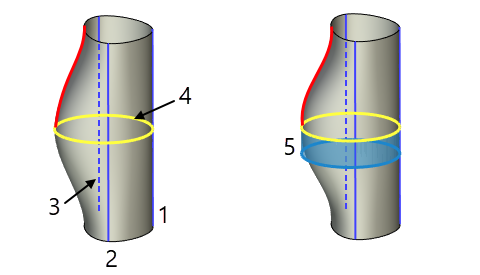
The boundary condition By Vectors for a guide works in the same way as the boundary condition for sections.
Without boundary condition |
Boundary condition |
|
|
||
1. Guide 2. Start points of vectors 1 and 2 3. Second point of vector 2 specifying the direction |
4. Vector 1 5. Vector 2 |
|
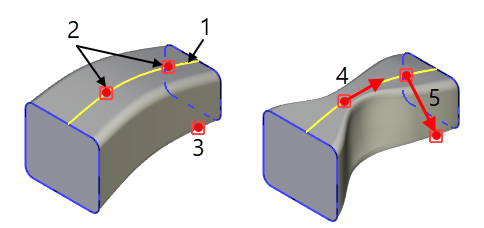
Boundary conditions for match points
For match points, only one boundary condition is available - By Vectors. It works similarly to the By Vectors boundary condition for sections. The only difference is that match points are used instead of first points.
Without boundary condition |
Boundary condition |
|
|
1. Match point of first section 2. Match point of second section |
|