Match Point of Loft |
  
|
Once the sections are defined, the system needs to relate them with each other. One needs to define how to configure the surface. This is what match points are for.
Automatically created starting match points |
Adjusted starting match points |
Matching points for sections with different number of vertices |
|
||
One match sequence is automatically created from the start points once the sections are defined. In complicated cases, however, this may not be enough.
|
|
1. First section 2. Second section 3. Start match |
4. Body with an "extra" edge 5. Additional match |
The sections are divided into sectors by the match points. Some of the generatrices of the surface being created pass exactly through the match points. The space between the sectors is divided into an equal number of elements for the primary generatrices to pass through. Should there be at least one vertex within a sector between any two match points on a section, the system subdivides the respective matching sectors in all sections in the same proportion. This is done to achieve an equal number of sectors in all sections. This may lead to creation of additional, sometimes undesired, edges and faces.

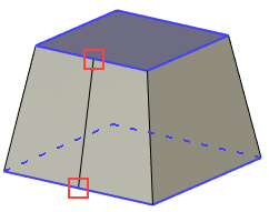
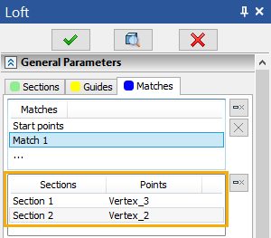
Therefore, an optimum solution is to define match points in the vertices of the sections. This way of defining the match points should be favored whenever possible. To switch to match point defining mode, go to the Matches tab of the operation parameters window. This tab hosts two related panes with the lists of sequences and the respective match points. Each sequence contains one point per a section, except for the single-point sections. The points are ordered from the start to the end section. The contents of the sequence can be viewed in the second pane.

General information when defining match points
Items that are selected as match points are highlighted in dark blue by default, and match start points are highlighted in blue. The active match point is highlighted in red.
|
1. Start match 2. Start match point 3. Match 4. Match point 5. Match (Active) 6. Match point (Active) |
To define a new sequence, place the cursor on a free line in the Match field. The system will then be ready to set points.
The first section is automatically highlighted in red (by default) - it becomes active. After selecting a point on the first section, the second is highlighted - and so on, until points on all sections are selected. Object snapping works - you can snap a point to the top of the section or to a 3D node on the section.
If snapping to vertices and nodes is not required, then you can create a point on the edge of the section. To select a point, point the cursor on the required edge and press ![]() .
.
Objects are selected in accordance with the current filter settings.
In this case, for the selected point, it will be possible to set the position on the edge.
The position of a point on an edge relative to the origin is determined by the U coordinate.The U coordinate implies two types of values:
•By Offset. For this type, the units of length must be considered.
•Parametric. For this type, the value has a unitless form (fraction of the length) from 0 to 1.
The system also provides the ability to select the base point of the U coordinate:
•Start. In this case, the base point is the starting point of the edge;
•Middle. In this case, the base point is the middle point of the edge;
•End. In this case, the base point is the end point of the edge;
The position of a point on an edge is set either manually using the Position field, or using a manipulator on a selected edge.
The direction of the edge coincides with the contour bypass direction.
It is not allowed to cross sequences of match points with each other.
To edit an object - a sequence or a point - you just need to select it in the parameters window, after which you can redefine it by selecting a new object in the 3D window. So, to edit an entire sequence (for example, a starting one), select the Start Points object in the Matches field, and then, in turn, indicate the required points on each section. Highlighting and object snapping works like the first time you set the sequence. To edit one point in the sequence, you must first select this point in the list of section-to-point relationships, then select another object in the 3D scene. When editing a point, the corresponding section is highlighted.
After editing the selected object, the system proceeds to change the next object in the list (point or sequence) or offers to set a new sequence if the edited object was the last in the list.
To remove any object from any field, select it and click the Delete Element button.
Auto-alignment
For successful automatic creation of the body, you need the same number of vertices on all sections. If the number of vertices is different, you can either manually set the match points, or use the auto-align match points option.
There are three types of auto-align match points - By Current Vertices, By Length, and Uniformly.
The first type automatically aligns the match points to the vertices of the sections.
Sections with 6 and 3 Vertices |
Auto-Alignment |
|
|
The second type automatically aligns the section match points so that spacing between adjacent edges has the same ratio to total length.
Sections with 6 and 3 Vertices |
Auto-Alignment "By Length" |
|
|
The third type aligns the match points of sections if at least one guide or one additional match is selected. If there are no guides and no matches, then the mode will work similarly to the previous type.
Auto-Alignment "By Length" |
Auto-Alignment "Uniformly" |
|
|
1. First section 2. Second section 3. Guide |
|
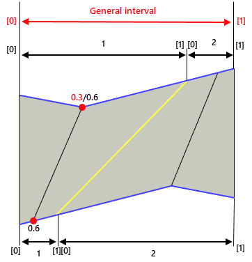
The above is an example where the guide (or match line) does not intersect other connection lines. If the guide intersects the connection lines, then the By Length type will not be able to handle such a case, and the result of the Uniformly type will be as follows:

The guide splits the sections into two intervals. The first point of the upper section has a general parameter equal to 0.3, and in the interval 1 (at the same point) its local parameter is 0.6. Accordingly, the interval point 1 is imprinted on the other section.
Synchronization
In the case when circles or ellipses with only one starting point act as sections, the option to synchronize the starting points may be useful. There are two types of synchronization - By Minimum Distance and By Minimum Twist.
The first type automatically sets the position of the match start points, ensuring the minimum distance between sections.
Auto-Alignment "By Length" without Synchronization |
Auto-Alignment "By Length" with Synchronization |
|
|
1. Match points and bypass directions |
|
The second type automatically sets the position of the match start points, ensuring the minimum twist. This option works only for closed and planar sections.
Auto-Alignment "By Length" with Synchronization |
Auto-Alignment "By Length" with Synchronization "By Minimum Twist" |
|
|
1. Match points and bypass directions |
|
Defining boundary conditions for match points is described in the Boundary Conditions section.