Main Concepts of Loft |
  
|
Main Concepts of Loft |
|
Sections
Sections define the surface shape along the first direction. To create a simplest instance of the operation, at least two sections need to be selected.
A section can be represented by either a surface or a wire object. A wire object may be either closed-loop or open. One section can be composed from several pieces that can be freely added and removed during the operation setup. The set of objects making one section must have same-type geometry. For example, one section can be composed of a set of paths and edges, or, alternatively, of a set of adjoining faces.
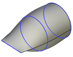
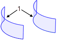
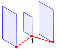
The section has such a parameter as the contour bypass direction. When specifying an operation on the selected section, an arrow is drawn in the direction of the bypass.
The direction of the contour bypass is used when calculating the surface; it must be the same for all selected sections. In most cases, the system can independently determine the direction of the sections to achieve a successful result. But if necessary, it can be changed by the user for each individual section.
|
1. Contour bypass direction 2. Sections |
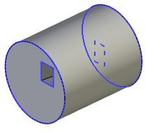
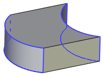
The contours of all sections used for creating the resulting surface must be of the same type – either open or closed. Exception is the case of a "clamped tube" body. In that case, most sections are defined by closed-loop sections, while the first or last section is defined by an open "wire". In order to successfully create such a body, follow precisely the set of conditions listed below.
|
1. Matching starting points 2. Additional matching points |
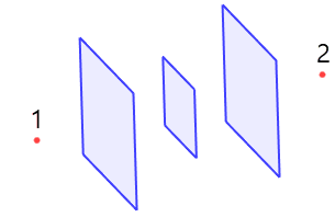
Multi-contour profiles can be used as sections, if they have same topology. For example, these can be similar profiles or copies of the same multi-contour profile. In this case, no other parameters may be specified (guides, matches, boundary conditions). When you select such a body in the Matching tab, you must additionally specify the Inner and Outer start points, some of which are the start points.
|
1. Inner starting point 2. Outer starting point |
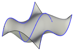
Sections can be planar or non-planar. For non-planar closed sections, variants of all boundary conditions are available.
|
1. Non-planar sections (3D Profiles) |
A point can be used as the first and last section. In this case, the surface will collapse in the selected end points.
|
1. First section (3D Node) 2. Last sections (3D Node) |
A detailed description of the selection of sections is described in the Section chapter.
Match point
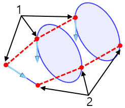
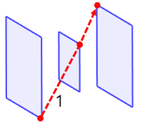
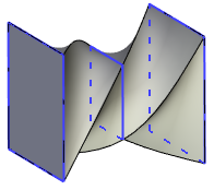
The match points help defining the direction of the surface propagation between the characteristic points of different sections. Always there is at least one match between the points in the sections. Originally, it is set between the start points of the sections. New sequences of match points can be added by the user manually. Any sequence of match points, including the start points, can be edited. The preview of the operation in the 3D window displays each set of match points connected by straight blue lines as soon as the elements get selected.
Each set of matching points includes one point from each section, except for the end sections defined by a single point The match points can be defined by 3D nodes, section vertices or the points defined on a section edge by the Position parameter.
|
1. Sequence of matching starting points |
If the end sections are open with the rest closed (as in the clamped tube body type), then the following conditions must be met when defining the match points:
1. At least two sequences of match points must be defined passing through the start and end of the first and last open wire.
2. The closed profiles should not have "free" vertices, that is, the vertices not used as match points in any sequence.
3. All match point sequences must meet at the start or end of the first and last open wires.
A detailed description of the selection of match points is described in the Match Point chapter.
Guides
Guides are similar to sections and are used for defining the shape of the resulting surface in the second direction. As opposed to sections, the guides can be made of wire geometry only. If a surface object is selected, its perimeter will be used instead. All objects must have continuous first derivative, that is, the "wire" should not have any sharp corners. Another condition is the requirement for a guide to intersect with all sections, including the ones defined by a single point. One guide can be composed of several smoothly connected linear objects.
|
1. Guides (3D Nodes) |
Guides can be closed or open. Closed guides are used for creating closed bodies.
A detailed description of the selection of guides is described in the Guides chapter.
Boundary conditions
Boundary conditions impose additional constraints on the shape of the resulting surface.
Different boundary conditions can be specified for different components of an operation. They are set in order to provide a more accurate surface, including the formation of smooth transitions.
For ordinary sections, you can set 4 boundary conditions - By Normal, By Tangent, By Geometry and By Vectors.
Ordinary sections are all sections except section-points.
For a section-point, as well as for match points, only one boundary condition is available - By Vectors.
For guides, only two boundary conditions are available - By Geometry and By Vectors.
A more detailed description of the boundary conditions is described in the Boundary Conditions chapter.
General information
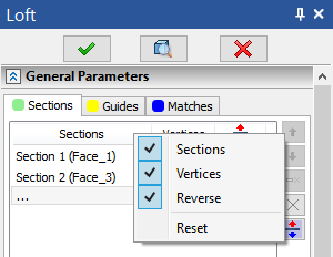
For each tab, you can customize the display of columns. For example, for sections, you can enable or disable the display of sections, the number of vertices, or reverse buttons.
You can change the contour bypass direction of sections/guides/matches either by disabling the Autoreverse option (see details in the corresponding section) ...
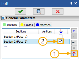
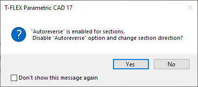
... or by pressing ![]() on the corresponding manipulator-arrow of contour bypass direction. In this case, the system will offer to first disable the Autoreverse option:
on the corresponding manipulator-arrow of contour bypass direction. In this case, the system will offer to first disable the Autoreverse option:
To edit a lofted body, use the corresponding command.